Schematic descriptions, 1 crd44800 pwm amplifier, 2 crd44800 driver board – Cirrus Logic CRD44800 User Manual
Page 3: 1 crd44800 pwm amplifier 1.2 crd44800 driver board
CRD44800
3
1. SCHEMATIC DESCRIPTIONS
1.1
CRD44800 PWM Amplifier
The CS44800 shown in Figure 5 employs a built-in Sample Rate Converter (SRC) to support
all popular sampling frequencies between 32 kHz and 192 kHz. The CS44800 produces a
PWM frequency of either 384 kHz or 768 kHz (refer to CS44800 data sheet). In this design,
analog or digital audio signals are always output at a 384 kHz PWM rate.
The CS4461 ADC is used to monitor the signal and line frequency related ripple that is inev-
itable on the power supply rail when the amplifiers operate. The ripple voltage is digitized
and fed back to the CS44800. The CS44800 uses this information to substantially reduce
ripple related distortion and noise in the audio output signal.
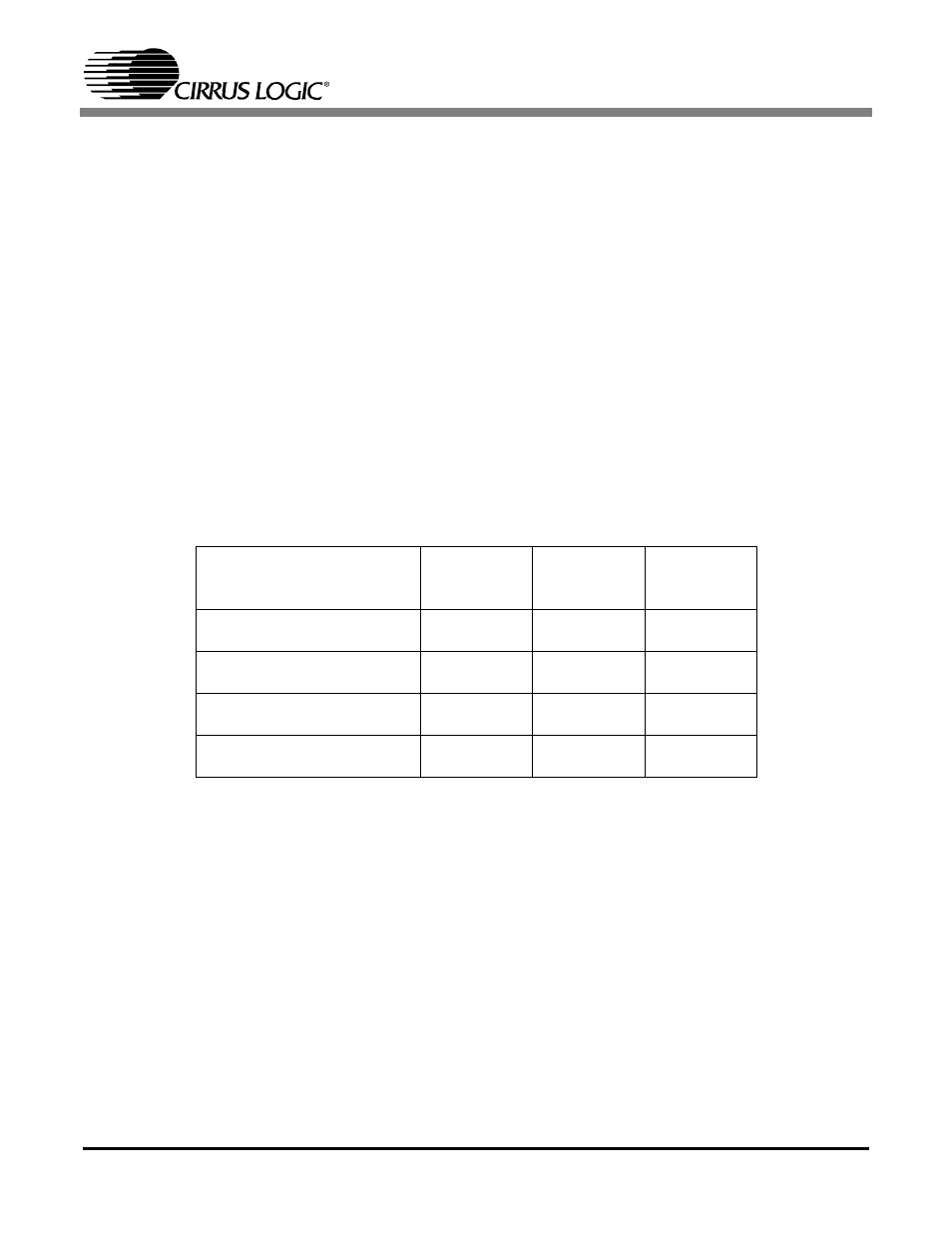
Four Philips TDA8939 power stages provide the power back end to drive the speaker loads.
Each TDA8939 consists of a pair of over current and temperature protected half-bridge PWM
output stages. The TDA8939 is performance optimized for use in open loop Class D amplifier
systems. By changing the power supply voltage and/or the load impedance, RMS output
power at the speaker can be increased. Table 1 illustrates measured RMS output voltage
when using the TDA8939 configured as a half-bridge:
1.2
CRD44800 Driver Board
The CRD44800 Driver board provides a convenient source of PCM I²S signals to drive the
CRD44800 PWM Amplifier board. Eight analog inputs allow multi-channel analog audio sig-
nals to be used for evaluation of the amplifier. In addition, either optical or coaxial stereo
S/PDIF signals can be used to evaluate the amplifier. In this case, the left and right channel
digital data are distributed to each of the additional channel pairs.
The CRD44800 Driver board provides two modes of operation: stand-alone and remote. In
the stand-alone mode, basic evaluation of the CS44800 is possible. The user can select be-
tween analog and digital S/PDIF input signals (jumpers J17 and J18), control the system vol-
ume, mute and unmute the system (switch S2), and ramp the PWM output up and down
(switch S3).
Supply Voltage
RMS Output
Power with an
8
Ω Load
RMS Output
Power with a
6
Ω Load
RMS Output
Power with a
4
Ω Load
45 V
1% THD+N
10% THD+N
25 W
38 W
33 W
50 W
47 W
70 W
50 V
1% THD+N
10% THD+N
32 W
47 W
41 W
61 W
57 W
86 W
55 V
1% THD+N
10% THD+N
38 W
57 W
50 W
74 W
69 W
105 W
60 V
1% THD+N
10% THD+N
44 W
67 W
58 W
88 W
81 W
124 W
Table 1. RMS Output Voltage for Given Load Impedance