5 dsd auto-mute (damute), 6 mute polarity and detect (mutep1:0), 9 mute control (address 09h) – Cirrus Logic CS4385 User Manual
Page 44: 1 mute (mute_xx), 1 mute (mute_xx), Cs4385
44
DS671F2
CS4385
6.8.5
DSD Auto-Mute (DAMUTE)
Function:
When set to 1 (default), the Digital-to-Analog converter output will mute following the reception of 256 re-
peated 8-bit DSD mute patterns (as defined in the SACD specification).
A single bit not fitting the repeated mute pattern (mentioned above) will release the mute. Detection and
muting is done independently for each channel. The quiescent voltage on the output will be retained, and
the Mute Control pin will go active during the mute period.
6.8.6
MUTE Polarity and DETECT (MUTEP1:0)
Default = 00
00 - Auto polarity detect, selected from MUTEC1 pin
01 - Reserved
10 - Active low mute polarity
11 - Active high mute polarity
Function:
Auto mute polarity detect (00)
Section 4.11 “The MUTEC Outputs” on page 30
for description.
Active low mute polarity (10)
When RST is low, the outputs are high impedance and will need to be biased active. Once reset has been
released and after this bit is set, the MUTEC output pins will be active low polarity.
Active high mute polarity (11)
At reset time, the outputs are high impedance and will need to be biased active. Once reset has been
released and after this bit is set, the MUTEC output pins will be active high polarity.
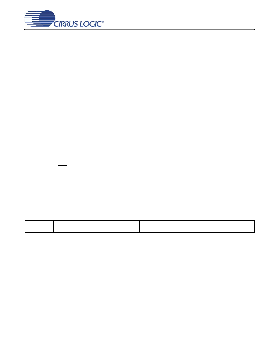
6.9
Mute Control (address 09h)
6.9.1
Mute (MUTE_xx)
Default = 0
0 - Disabled
1 - Enabled
Function:
The Digital-to-Analog converter output will mute when enabled. The quiescent voltage on the output will
be retained. The muting function is affected, similarly to attenuation changes, by the Soft and Zero Cross
bits. The MUTE pins will go active during the mute period according to the MUTEC bit.
7
6
5
4
3
2
1
0
MUTE_B4
MUTE_A4
MUTE_B3
MUTE_A3
MUTE_B2
MUTE_A2
MUTE_B1
MUTE_A1
0
0
0
0
0
0
0
0