Dc electrical characteristics, Digital characteristics, Cs4272 – Cirrus Logic CS4272 User Manual
Page 17
CS4272
DS593F1
17
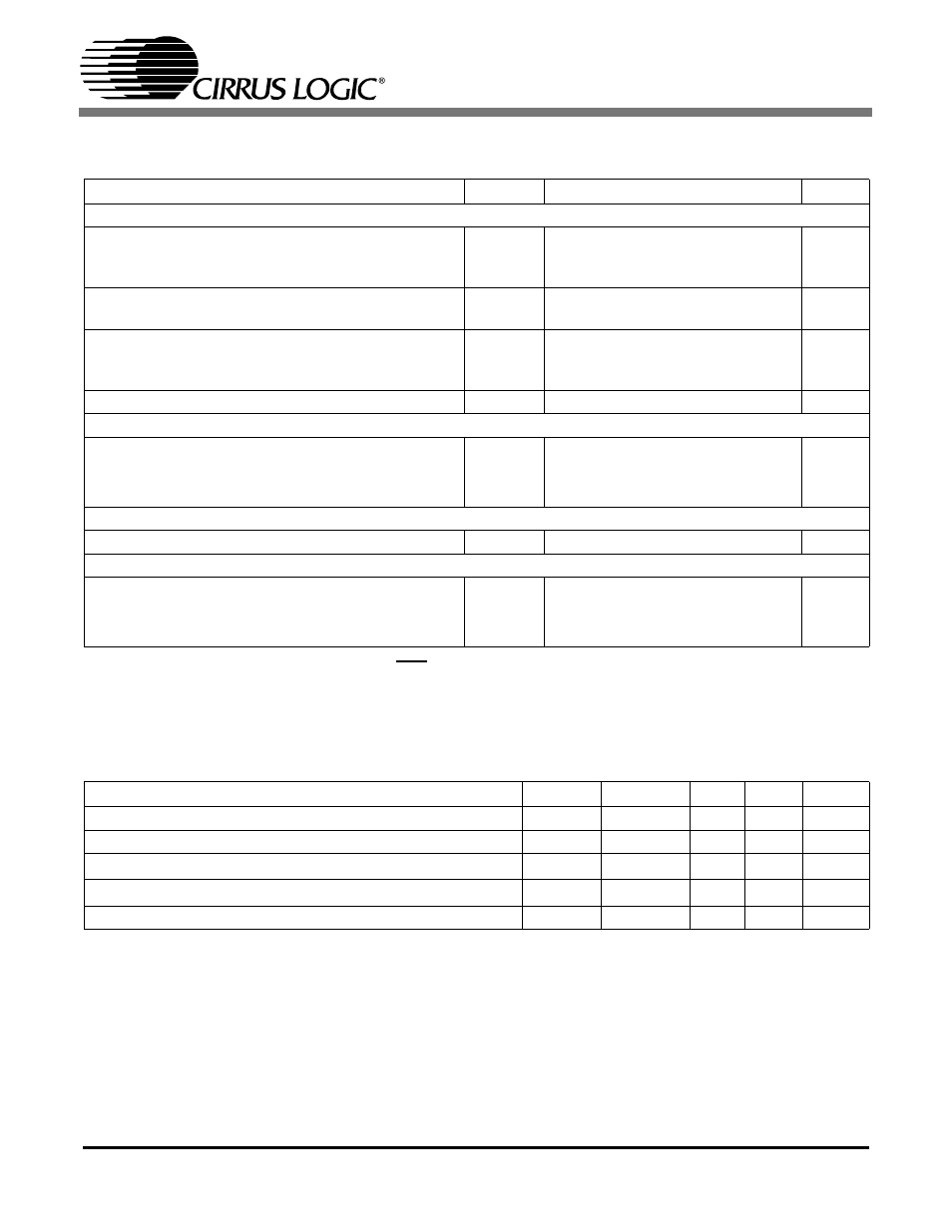
DC ELECTRICAL CHARACTERISTICS
(GND = 0 V, all voltages with respect to ground. MCLK=12.288 MHz; Master Mode)
Notes: 20. Power Down Mode is defined as RST = Low with all clocks and data lines held static.
21. Valid with the recommended capacitor values on FILT+ and VCOM as shown in the Typical Connection
Diagram.
DIGITAL CHARACTERISTICS
Parameter
Symbol
Min
Typ
Max
Unit
Power Supply
Power Supply Current
VA
(Normal Operation)
VL,VD = 5 V
VL,VD = 3.3 V
I
A
I
D
I
D
-
-
-
45
41.5
24
53
49
28
mA
mA
mA
Power Supply Current
VA
(Power-Down Mode)(Note 20)
VL,VD=5 V
I
A
I
D
-
-
0.025
1.76
-
-
mA
mA
Power Consumption
VL, VD=5 V
(Normal Operation)
VL, VD = 3.3 V
(Power-Down Mode)
-
-
-
-
-
-
433
305
9
510
358
-
mW
mW
mW
Power Supply Rejection Ratio
(1 kHz)
(Note 21)
PSRR
-
60
-
dB
Common Mode
Nominal Common Mode Voltage
VCOM
-
0.48xVA
-
VDC
Maximum DC Current Source/Sink from VCOM
-
1
-
µA
VCOM Output Impedance
-
25
-
k
Ω
FILT+
FILT+ Nominal Voltage
FILT+
-
VA
-
VDC
MUTEC
MUTEC Low-Level Output Voltage
-
0
-
V
MUTEC High-Level Output Voltage
-
VA
-
V
Maximum MUTEC Drive Current
-
3
-
mA
Parameter
Symbol
Min
Typ
Max
Units
High-Level Input Voltage
(% of VL)
V
IH
70%
-
-
V
Low-Level Input Voltage
(% of VL)
V
IL
-
-
30%
V
High-Level Output Voltage at I
o
= 2 mA
V
OH
VL - 1.0
-
-
V
Low-Level Output Voltage at I
o
= 2 mA
V
OL
-
-
0.4
V
Input Leakage Current
I
in
-
-
±10
µA