4 analog input multiplexer, pga, and mic gain, Figure 14. analog input architecture, 5 input connections – Cirrus Logic CS4245 User Manual
Page 34: 6 output connections, Figure 14.analog input architecture, Cs4245
34
DS656F3
CS4245
4.4
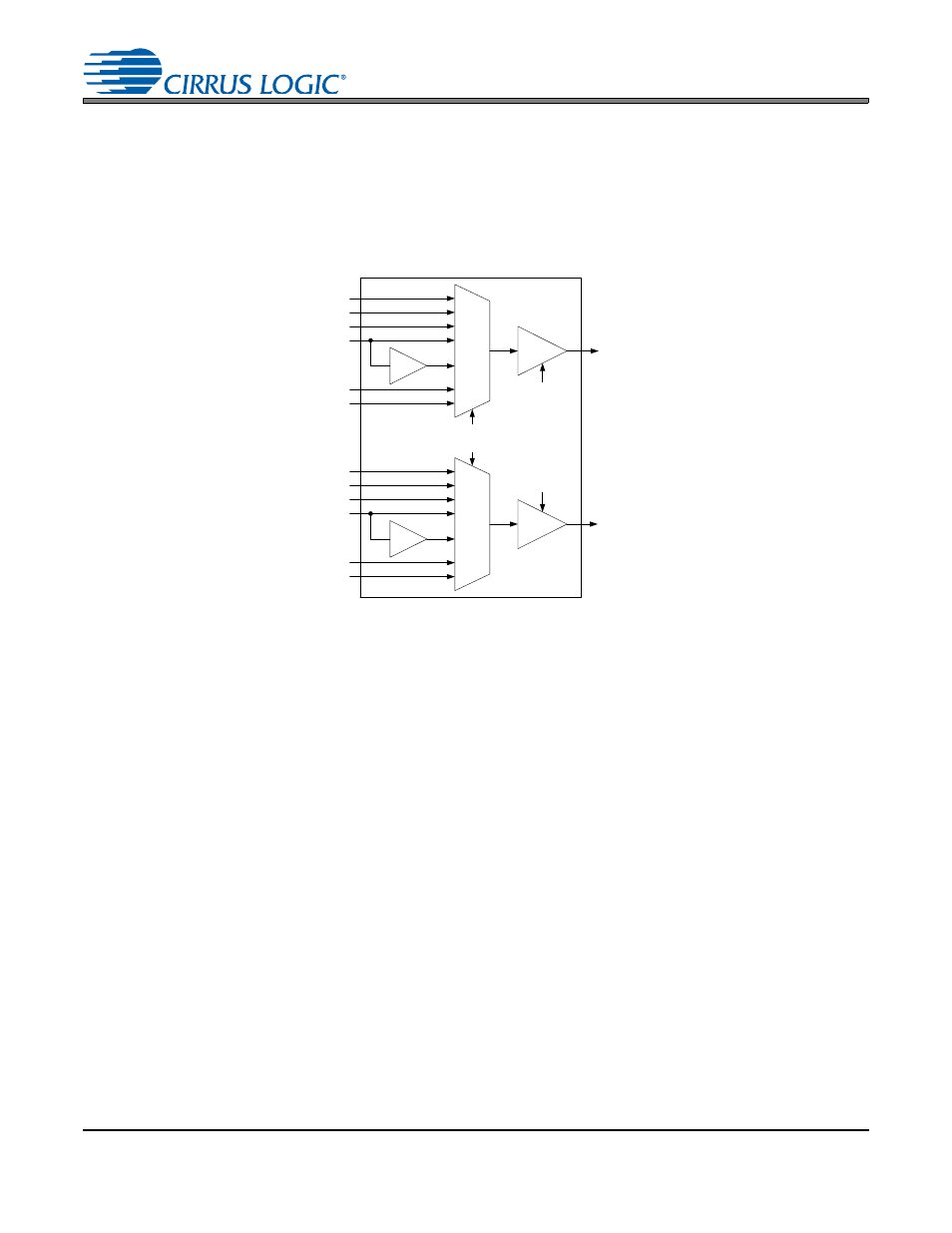
Analog Input Multiplexer, PGA, and Mic Gain
The CS4245 contains a stereo 6-to-1 analog input multiplexer followed by a programmable gain amplifier
(PGA). The input multiplexer can select one of six possible stereo analog input sources and route it to the
PGA. Analog inputs 4A and 4B are able to insert a +32 dB gain stage before the input multiplexer, allowing
them to be used for microphone-level signals without the need for any external gain. The PGA stage pro-
vides 12 dB of gain or attenuation in 0.5 dB steps.
shows the architecture of the input multiplex-
er, PGA, and microphone gain stages. .
The
“Analog Input Selection (Bits 2:0)” on page 48
outlines the bit settings necessary to control the input
multiplexer and mic gain.
“Channel B PGA Control - Address 07h” on page 47
outline the register settings necessary to control the PGA. By default, line-
level input 1 is selected, and the PGA is set to 0 dB.
4.5
Input Connections
The analog modulator samples the input at 6.144 MHz (MCLK=12.288 MHz). The digital filter will reject sig-
nals within the stopb and of the f ilter. However, there is no rejection for input signals which a re
(n
6.144 MHz) the digital passband frequency, where n=0,1,2,... Refer to the Typical Connection Diagram
for the recommended analog input circuit that will attenuate noise energy at 6.144 MHz. The use of capac-
itors which have a large voltage coefficient (such as general-purpose ceramics) must be avoided since
these can degrade signal linearity. Any unused analog input pairs should be left unconnected.
4.6
Output Connections
The CS4245 DACs implement a switched-capacitor filter, followed by a continuous time low-pass filter. Its
response, combined with tha t of the digital interpolator, is sh own in
Section 8. “DAC Filter Plots” on
”. The recommended external analog circuitry is shown in the Typical Connection Diagram.
The CS4245 DAC does not include phase or amplitude compensation for an external filter. Therefore, the
DAC system phase and amplitude response is dependent on the external analog circuitry.
PGA
MUX
+32 dB
AIN1A
AIN2A
AIN3A
AIN4A/MICIN1
AIN5A
AIN6A
PGA
MUX
+32 dB
AIN1B
AIN2B
AIN3B
AIN4B/MICIN2
AIN5B
AIN6B
Analog Input
Selection Bits
Channel A
PGA Gain Bits
Channel B
PGA Gain Bits
Out to ADC
Channel A
Out to ADC
Channel B
Figure 14. Analog Input Architecture