Figure 12. ratio feature summary, 5 pll clock output, Figure 13. pll clock output options – Cirrus Logic CS2100-OTP User Manual
Page 16: Cs2100-otp, 1 mux
CS2100-OTP
16
DS841F2
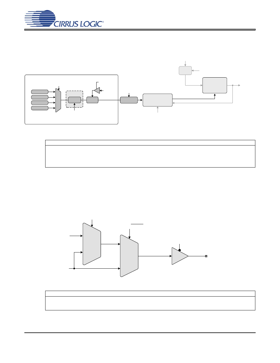
final calculation used to determine the output to input clock ratio. The effective ratio is then corrected for
the internal dividers. The conceptual diagram in
summarizes the features involved in the calcu-
lation of the ratio values used to generate the fractional-N value which controls the Frequency Synthesiz-
er. The subscript ‘4’ indicates the modal parameters.
Figure 12. Ratio Feature Summary
5.5
PLL Clock Output
The PLL clock output pin (CLK_OUT) provides a buffered version of the output of the frequency synthesizer.
The driver can be set to high-impedance with the M2 pin when the M2Config[1:0] global parameter is set to
either 000 or 010. The output from the PLL automatically drives a static low condition while the PLL is un-
locked (when the clock may be unreliable). This feature can be disabled by setting the ClkOutUnl global
parameter, however the state CLK_OUT may then be unreliable during an unlock condition.
Figure 13. PLL Clock Output Options
Referenced Control
Parameter Definition
Ratio 0-3................................
M[1:0] pins.............................
“M1 and M0 Mode Pin Functionality” on page 17
LFRatioCfg ............................
“Low-Frequency Ratio Configuration (LFRatioCfg)” on page 22
RModSel[1:0] ........................
“R-Mod Selection (RModSel[1:0])” section on page 20
RefClkDiv[1:0] .......................
“Reference Clock Input Divider (RefClkDiv[1:0])” on page 21
Referenced Control
Parameter Definition
ClkOutUnl..............................
“Enable PLL Clock Output on Unlock (ClkOutUnl)” on page 22
ClkOutDis ..............................
“M2 Configured as Output Disable” on page 18
M2Config[2:0]........................
“M2 Pin Configuration (M2Config[2:0])” on page 22
Effective Ratio R
EFF
Ratio Format
Frequency Reference Clock
(CLK_IN)
SysClk
PLL Output
Frequency
Synthesizer
Digital PLL &
Fractional N Logic
Ratio 0
Ratio 1
Ratio 2
Ratio 3
12.20
20.12
M[1:0] pins
LFRatioCfg
RModSel[1:0]
4
Ratio
Modifier
R Correction
RefClkDiv[1:0]
Timing Reference Clock
(XTI/REF_CLK)
Divide
RefClkDiv[1:0]
Dynamic Ratio, ‘N’
User Defined Ratio R
UD
M2 pin
PLL Locked/Unlocked
PLL Output
2:1 Mux
M2 pin with
M2Config[1:0] = 000, 010
2:1 Mux
ClkOutUnl
0
PLL Clock Output Pin
(CLK_OUT)
0
1
0
1
PLL Clock Output
PLLClkOut