Installing the controller, Power button left, Button right – Antennas Direct ROTR100 User Manual
Page 4: Button 3 digit led display power indicator
FROM CONTROLLER
USE 2 CABLE BOOTS
TO ANTENNA
RG6 COAX
MAIN DOWNLEAD
ROTATOR
INPUT
ROTATOR RECEIVER
BACK OF CONTROLLER
FIG 4:
SINGLE COAX CABLE INSTALLATION WITH
COMPATIBLE PREAMPLIFIER
SHORT STUB-MAST
DRIVE UNIT
OUTPUT TO RECEIVER (TV)
DRIP LOOP
(OPTIONAL)
PREAMPLIFIER
IN
PREAMPLIFIER
OUT
ONLY A COMPATIBLE
PREAMPLIFIER MAY BE USED
IN THIS CONFIGURATION
FROM CONTROLLER
USE 1 CABLE BOOT
AND 1 BLANKING BOOT
TO ANTENNA
NOT CONNECTED
PREAMPLIFIER
(OPTIONAL)
TO RECEIVING (TV) EQUIPMENT
(OR PREAMP POWER SUPPLY)
RG6 COAX
RG6 COAX
ROTATOR
INPUT
ROTATOR RECEIVER
BACK OF CONTROLLER
FIG 5:
SEPARATE ROTATOR AND ANTENNA
CABLE INSTALLATION
SHORT STUB-MAST
DRIVE UNIT
RECEIVER (TV) OUTPUT
NOT CONNECTED
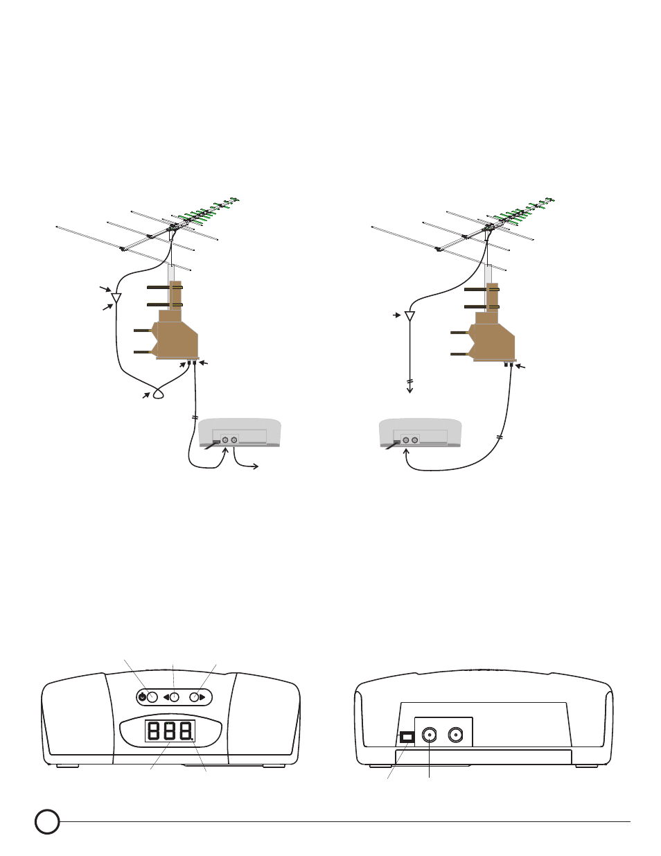
2. USING SEPARATE COAX CABLES FOR THE ANTENNA AND THE ROTATOR.
If it is NOT desired to use the rotator's power coax for passing VHF/UHF signals, or it is desired to
use a preamplifier that does NOT conform to the specification of +17 VDC at less than 50mA power,
then a separate coax cables must be used for the signal feed and rotator power/control feed.
See Fig 5
" Install a separate VHF/UHF signal coax cable for the antenna (and pre-amp, if used).
" Do not connect anything to the drive unit's “TO ANTENNA” jack, but do install the supplied, rubber
blanking weather boot.
" Do not connect anything to the controller's “RECEIVER” jack.
Power
Button
Left
(Counter Clockwise)
Button
Right
(Clockwise)
Button
3 Digit
LED Display
Power
Indicator
INSTALLING THE CONTROLLER
" Install the controller within range of the infra-red handheld remote control.
" Connect as shown in Fig 4 or Fig 5.
120 VAC Power Cord
18VDC Out
ROTATOR RECEIVER
4
ROTR-100 INSTALLATION GUIDE
120 VAC
120 VAC