Operation flow chart – WIKA CF1M User Manual
Page 4
Operating Instructions Temperature Indicating Controller CF1M
V1.
1
•
03/200
5
- 4 -
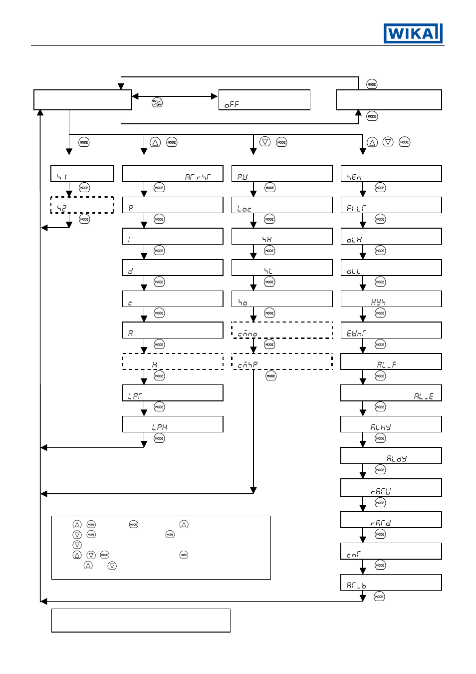
3.1
Operation flow chart
PV/SV display mode
(Approx. 1s)
Control output OFF function
[
]
Output manipulating value display
(Approx. 3s)
+
+
(Approx. 3s)
+
+
(Approx. 3s)
[Main setting mode] [Sub setting mode] [Auxiliary function setting mode 1] [Auxiliary function setting mode 2]
Main setting 1
[
]
AT Perform/Cancel or
Auto reset Perform
[
/
]
PV/SV display change
[
]
Sensor selection
[
]
Main setting 2
[
]
Proportional band value setting
[ ]
Setting value lock designation
[
]
PV filter time constant setting
[
]
Integral time setting
[ ]
Main setting value high limit
setting [
]
Output high limit setting
[
]
Derivative time setting
[ ]
Main setting value low limit
setting [
]
Output low limit setting
[
]
Proportional cycle setting
[ ]
Sensor correction setting
[
]
Output ON/OFF hysteresis
setting [
]
Temperature alarm setting
[ ]
Instrument number setting
[
]
Event output function selection
[
]
Heater burnout alarm output
setting [ ]
Transfer rate setting
[
]
Temperature alarm action
selection [
]
Loop break alarm time setting
[
]
Temperature alarm energized/
deenergized selection [
]
Loop break alarm action span
setting [
]
Temperature alarm hysteresis
setting [
]
Temperature alarm delayed
timer setting [
]
Main setting value rising rate
setting [
]
Main setting value falling rate
setting [
]
Output Direct/Reverse change
[
]
Auto-tuning bias setting
[
]
+
: Press the
key while the
key is being pressed.
+
(Approx. 3s): Press the
key for 3 seconds while the
key is being pressed.
+
+
(Approx. 3s): Press the
key for 3 seconds while
the
and
key are being pressed.
The functions with dashed frames are optional
and not active for every controller !