WIKA A-AI-2 User Manual
Page 13
6 Commissoning, operation
WIKA operating instructions, model A-AI-2
13
Standard assignment of angular plug (A-AI-2-S)
contact number
wire colour
pin
jack
1 blue
indicator
+
indicator
-
2
red
connected
3 black
connected
4
yellow
connected
In the angle-type plug the male contacts 2, 3 and 4 are
directly connected 1:1 with the socket. Device is
located between the male contact 1 (+) and the jack
contact 1 (-).
If the '-Ub'-line is not assigned to contact 1, please do not forget to adjust the angle-type plug and the
external angle-type plug accordingly: To do so open the angle-type plug (refer to the “general
instructions for change ....”) and exchange the wire of contact 1 against the wire of the contact
representing the connection in your transmitter.
Then exchange and rewire the two contacts in the angle-type plug of your connecting cable.
General instruction for change of the angular plug assignment
Remove the coupling insert by means of a screw driver at the position indicated (arrow). Change the
assignment according the notes of the respective input signal.
Latch coupling insert in cover. You have a choice between 4 different orientations – each of them
spaced 90°. Put on angel-type plug and connect plugs using the long screw delivered (do not forget
seals).
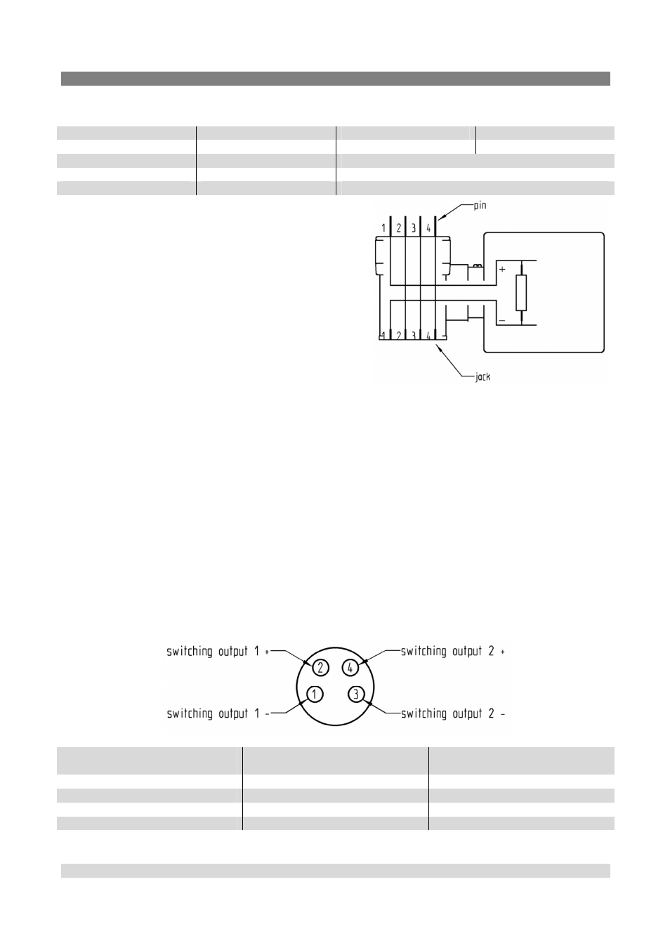
Terminal assignment of the switching outputs
assignment of the M8-
connector
assignment of the connection
cable EBK401
description
1
brown
switching output 1 -
2
white
switching output 1 +
3
blue
switching output 2 -
4
black
switching output 2 +