Instruction manual ni-221e – WIKA MAB User Manual
Page 4
INSTRUCTION MANUAL
NI-221E
Rev. 1 11/02
5.3.1 Weatherproof pressure switches (Series MW)
Take the cover, ensure that the sealing gasket is correctly
fitted into its seat, and insert the cover onto the case, with
the blocking gap positioned in correspondence to the
blocking bracket.
Turn the cover clockwise closing it tightly.
Mount the blocking device as in Fig. 3.
5.3.2 Explosionproof pressure switches (Series MA).
Screw on the cover and block it using the headless screw
with which it is equipped (Fig. 4)
Mount on pressure connection and cable entry the protec-
tion caps supplied with the instrument. The protection
caps should only be definitively removed during the con-
nection steps (see § 6).
6
MOUNTING AND CONNECTIONS
6.1 MOUNTING
Surface mount the instrument by means of the holes
provided, or pipe mount using the appropriate bracket
(see Fig. 9).
The chosen position must be such that vibrations, the
possibility of shocks or temperature changes are within
tolerable limits. The above also applies to direct mounting.
With gas or vapour process fluid, the instrument must be
positioned higher than the pipe inlet (see Fig. 8). With a
liquid process fluid, the instrument can be positioned
higher or lower, indifferently (see Fig. 7 e 8). ). In this
case, during set point calibration the negative or positive
head must be taken into account (distance h in Fig.7 e 8).
6.2 PRESSURE CONNECTIONS
For a correct installation it is necessary to:
Mount a shut-off valve with drain (root valve) on the proc-
ess tube to allow the instrument to be excluded and the
connection tubing to be drained. It is recommended that
said valve has a capstan-blocking device aimed at pre-
venting it being activated casually and without authorisa-
tion. Mount a service valve near the instrument to permit
possible functional verification on site. It is recommended
that the service valve is closed with a plug to prevent the
outlet of the process fluid caused by the incorrect use of
said valve. Mount a three-piece joint onto the threaded
attachment of the instrument to permit the easy mounting
or removal of the instrument itself. Carry out the connec-
tion using a flexible tube in such a way that variations in
the temperature of the tube itself do not force the instru-
ment attachment. Ensure that all the pressure connections
are airtight. It is important that there are no leakages in
the circuit. Close the root valve and the relative drain
device. Close the service valve using a safety plug.
6.3 ELECTRICAL CONNECTIONS
It is recommended to carry out the electrical connections
according to the applicable standards. In case of explo-
sionproof instruments (Series MA) see also the Standard
EN-60079-14. If the electrical connection is carried out in
a protected tube, it shall be made so that condensate is
prevented from entering instrument enclosure.
The arrangement shown in Fig. 7 or 8 is therefore recom-
mended..
CAUTION:
fittings used for the electrical connection of
the pressure switch Series MA (explosionproof) shall be
certified to Standards EN 50014 and 50018, and shall
guarantee instrument degree of protection (IP65).
Check that there is no power in the lines.
Remove the cover and carry out the cabling and connec-
tions to the terminal block (see Fig. 2).
Flexible cables with a maximum section of 1.2 mm
2
(16AWG) are recommended using the pre-insulated fork
thimbles. Do not touch the adjustment screws and do
not bend the elastic microswitch supports in order to
prevent the instrument calibration being altered.
Ensure that no deposits or wire ends remain inside the
case.
As soon as connection steps are completed, mount the
cover on and make sure it is tight and blocked See Fig. 3
and 4.
6.4
SPECIAL NOTE FOR INSTALLATION OF
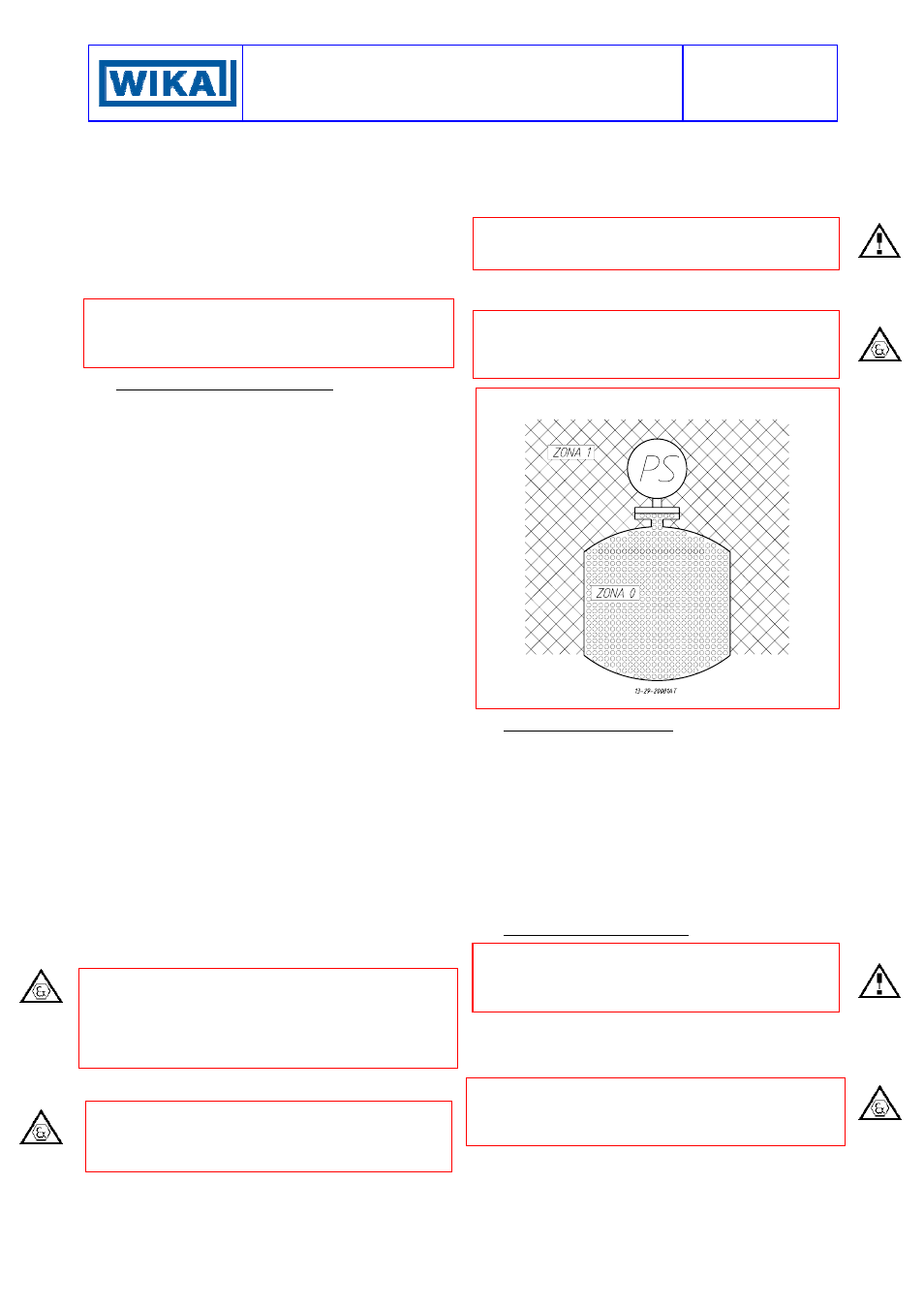
CATEGORY 1 / 2 G PRESSURE SWITCHES
Explosionproof pressure switches (Series MA) can be
installed on processes requiring apparatus of group II
category 1 in an ambient requiring apparatus of group II
category 2 (see Fig. 6).
Fig. 6 -
Installation of Group II Cat. 1 / 2 G instruments
7 INSTRUMENT
PLUMBING
7.1 Weatherproof pressure switches (Series MW)
The plumbing, aimed as a guarantee against possible
tampering of the calibration and electrical connections,
can be carried out using a flexible steel wire (c) inserted
into the holes in the screw (a) and the bracket (e) provided
for this purpose (see Fig. 3).
7.2 Explosionproof pressure switches (Series MA )
Plumbing is not necessary as the cover is blocked with a
headless screw and the instrument does not have to be
opened when installed (see Fig. 4).
8
PUTTING INTO OPERATION
As the signal transmitted by the instrument is used in a
complex system, it is necessary that the means of putting
it into operation are established by those in charge of the
plant.
The instrument comes into operation as soon as the root
valve is opened. Any possible drainage of the connection
tubing can be carried out by removing the safety plug and
opening the service valve with the necessary caution.
In case of explosionproof instruments (Series MA), initial
inspections are to be carried out according to customer
procedures and at least in accordance with Standard EN-
60079-17.