Instruction manual ni-221e – WIKA MAB User Manual
Page 3
INSTRUCTION MANUAL
NI-221E
Rev. 1 11/02
If the instrument has been ordered with a specific cali-
bration, it is a good rule to check the calibration values
marked on the relevant adhesive label, prior to installation.
The position of the adjustment screw is given in figure 2.
The effect that the direction of rotation of the adjustment
screw has is described on the adhesive plate.
5
SET POIT CALIBRATION
In order to proceed with the calibration and the periodical
functional verification of the instrument a suitable calibra-
tion circuit (fig. 4) and an adequate pressure source is
required.
5.1 PRELIMINARY OPERATIONS
5.1.1 Weatherproof pressure switches (Series MW)
Remove the blocking device fixed to the side of the in-
strument case (Fig. 3).
Remove the cover by rotating it in an anticlockwise direc-
tion.
Fig. 3 -
Weatherproof pressure switch blocking device
a - Plumbing wire
b - Plumbing
c - Nut
d - Blocking bracket
5.1.2 Explosionproof pressure switches (Series MA)
CAUTION: do not open the cover of explosionproof pres-
sure switches (Series MA) when energized, in explosive
atmospheres.
Loosen the locking headless screw situated on the cover
using a 1,5 hexagonal key then unscrew the cover. (Fig.
4).
Fig. 4 -
Explosionproof pressure switch blocking device
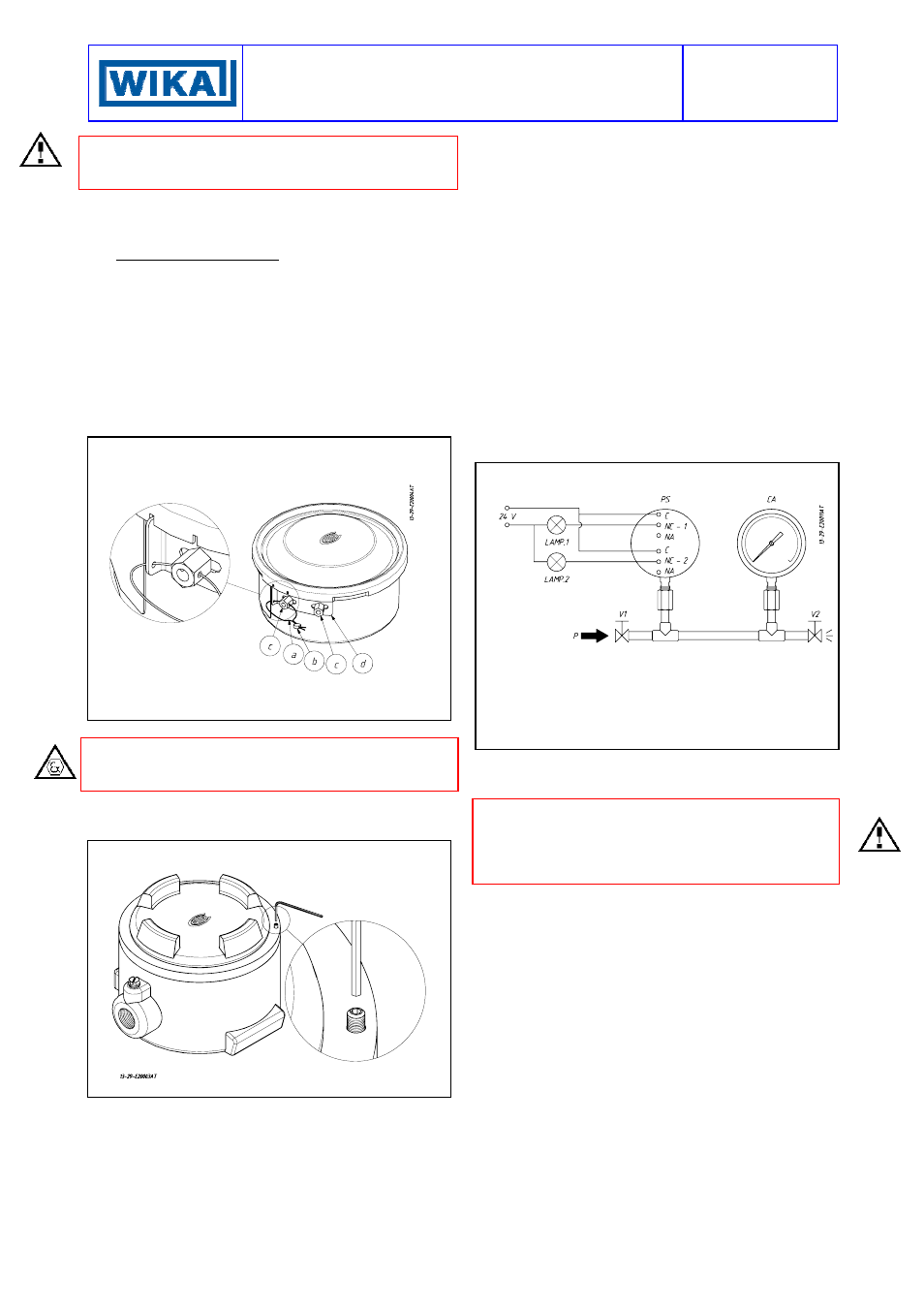
5.2 CALIBRATION CIRCUIT AND OPERATIONS
Prepare the control circuit as indicated in Fig.5.
The warning lamps should be connected to contact 1 or 2
in the NO or NC position according to the required contact
action.
Connection of C and NO terminals
• If the circuit is open at the working pressure, the switch
closes the circuit as the pressure increases when the
desired value is reached.
• If the circuit is closed at the working pressure, the switch
opens the circuit as the pressure decreases when the
desired value is reached.
Connection of C and NC terminals
• If the circuit is closed at the working pressure, the switch
opens the circuit as the pressure increases when the
desired value is reached.
• If the circuit is open at the working pressure, the switch
closes the circuit as the pressure decreases when the
desired value is reached.
The test instrument should have a measurement range
approximately equal to or slightly wider than the pressure
switch range and should have an accuracy consistent with
the precision required to calibrate the set point.
The pressure switch must be mounted in the normal in-
stallation position, i.e. with the pressure connection point-
ing downwards.
Fig. 5 -
Calibration circuit
PS -
Pressure switch
CA -
Test pressure gauge
V1 -
Inlet valve
V2 -
Discharge valve
P -
Pressure source
Test fluid:
air for P
≤ 10 bar
water for P > 10 bar
Avoid forcing the elastic support of the microswitch by
hand or with tools. This could affect the instrument func-
tioning.
CAUTION: if the switch is of the kind with adjustable dead
band (letter R in the contact codes) before proceeding
with the following operations it is necessary to proceed
with the adjustment of the dead band (see attachment NI-
706).
Increase the pressure in the circuit up to the desired set
point value for the first microswitch. Use a wide bladed
screwdriver, as indicated on the adhesive plate, until the
relative lamp turns on (or turns off).
- If the instrument is equipped with only one contact the
calibration is complete.
- If it is equipped with two contacts continue in the follow-
ing manner.
Vary the pressure until the desired set point value for the
second microswitch is reached. Act on the adjustment
screw of the second contact
.
Repeat calibrating operations on the first contact, then on
the second contact, until the required set point precision is
obtained. This is necessary due to the reciprocal influence
which the microswitches have on the sensitive element of
the instrument.
Check the calibration values (varying the pressure in the
circuit accordingly) and record them on the adhesive plate
using a pen with indelible ink.
5.3 FINAL OPERATIONS
Disconnect the instrument from the calibration circuit.