Switch contacts – WIKA DPGS43HP.160 User Manual
Page 8
8
080
50 07/
009 GB/D/F
GB
WIKA Operating instructions pressure gauges Model 7 with 831 per ATEX
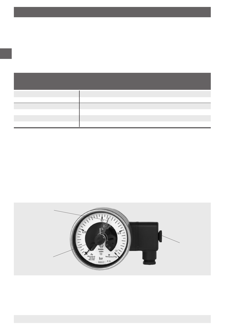
4. Switch contacts
Red set pointer
Adjustment
lock
Removable
adjustment key
Circuit
Sensor type Model designation
EC-type exami-
WIKA-
(s. Ex-certific.)
Fa. Pepperl & Fuchs
nation certificate
Model
Model 1
standard
KFD2-SR2-Ex1
PTB 00 ATEX 2080
904.31
standard
KFD2-SR2 Ex2
PTB 00 ATEX 2080
904.32
Model 2
standard
KFA6-SR2-Ex1
PTB 00 ATEX 2081
904.28
standard
KFA6-SR2-Ex2
PTB 00 ATEX 2081
904.29
SN-sensors
KFD2-SH-Ex1
PTB 00 ATEX 2042
904.33
SN-sensors
KHA6-SH-Ex1
PTB 00 ATEX 2043
904.30
The permissible limits of U
i
, I
i
and P
i
for the intrinsically safe supply circuits
depend on the sensor type. They can be taken from the corresponding EC-type
examination certificates. (The sensor type is stated on the connection plate of
the pressure gauge.)
Suitable switch amplifiers are e.g.:
Electromagnetic compatibility
EMC to EN 60 947-5-.
The instruments must be protected against strong electromagnetic fields.
Adjusting red set pointers
The setting of the set point is achieved using the adjustment lock in the window
with the aid of the adjustment key (part of the scope of supply; found in
standard instruments on the side of the terminal box).
The set point indicators for the switch contacts are freely adjustable over the
full scale range. For reasons of switching accuracy and long life of the mechani-
cal measuring system, the switching points should be between 10 % and 90 %
of the measuring range.