Instruction manual ni-222e – WIKA BWX User Manual
Page 4
INSTRUCTION MANUAL
NI-222E
Rev. 1 12/02
• If the circuit is open at the working pressure, the
switch closes the circuit as the pressure decreases
when the desired value is reached.
The test instrument should have a measurement range
approximately equal to or slightly wider than the pressure
switch range and should have an accuracy consistent
with the precision required to calibrate the set point.
The pressure switch must be mounted in the normal
installation position, i.e. with the pressure connection
pointing downwards.
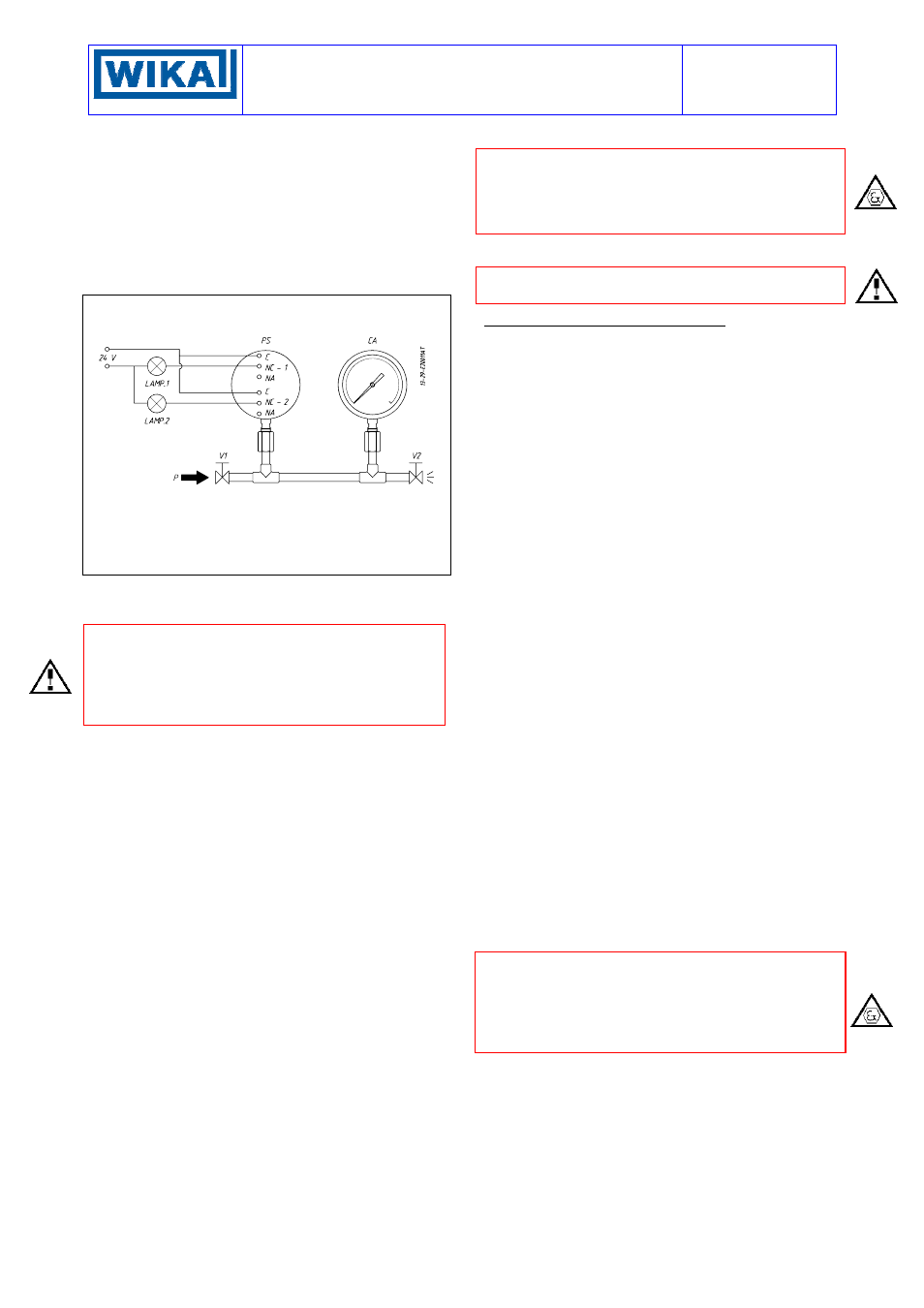
Fig. 5 -
Calibration circuit
PS -
Pressure switch
CA -
Test pressure gauge
V1 -
Inlet valve
V2 -
Inlet valve
P -
Pressure source
Test fluid:
air for P
≤ 10 bar
water for P > 10 bar
Avoid forcing the elastic support of the microswitch by
hand or with tools. This could affect the instrument func-
tioning.
CAUTION: if the switch is of the kind with adjustable
dead band (letter R in the contact codes) before pro-
ceeding with the following operations it is necessary to
proceed with the adjustment of the dead band (see at-
tachment NI-705 for model BWXUR and NI-704 for
model BAXUR)
Increase the pressure in the circuit up to the desired set
point value for the first microswitch.
Use a wide bladed screwdriver, as indicated on the ad-
hesive plate, until the relative lamp turns on (or turns off).
- If the instrument is equipped with only one contact the
calibration is complete.
- If it is equipped with two contacts continue in the fol-
lowing manner.
Vary the pressure until the desired set point value for the
second microswitch is reached.
Act on the adjustment screw of the second contact.
Repeat former operations on the first contact, then op-
erations on the second contact, until the required set
point precision is obtained. This is necessary due to the
reciprocal influence which the microswitches have on the
sensitive element of the instrument.
Check the calibration values (varying the pressure in the
circuit accordingly) and record them on the adhesive
plate using a pen with indelible ink.
5.3 FINAL OPERATIONS
Disconnect the instrument from the calibration circuit
Weatherproof pressure switches (Series BWX)
Take the cover, ensure that the sealing gasket is cor-
rectly fitted into its seat, and insert the cover onto the
case, with the blocking gap positioned in correspon-
dence to the blocking bracket. Turn the cover clockwise
closing it tightly. Mount the adjustment screw access
plate, then the blocking device as in Fig. 3.
Explosionproof pressure switches (Series BAX).
Insert the closure plugs of the adjustment screw access
holes, block them using the internal device and if nec-
essary seal them with plumbing. Screw on the cover and
block it using the headless screw with which it is
equipped (Fig. 4).
Replace the supplied protection caps on the pressure
attachment and cable conduit.
IMPORTANT: the protection caps should only be defini-
tively removed during the connection steps (see §6).
6 - MOUNTING AND CONNECTIONS
6.1 MOUNTING
Surface mount the instrument by means of the holes
provided, or pipe mount using the appropriate bracket
(see Fig. 9). The chosen position must be such that
vibrations, the possibility of shocks or temperature
changes are within tolerable limits. The above also ap-
plies to direct mounting. With gas or vapour process
fluid, the instrument must be positioned higher than the
pipe inlet (see Fig. 8). With a liquid process fluid, the
instrument can be positioned higher or lower, indiffer-
ently (see Fig. 7 e 8). ). In this case, during set point
calibration the negative or positive head must be taken
into account (distance h in fig.7 and 8).
6.2 PRESSURE CONNECTIONS
For a correct installation it is necessary to:
Mount a shut-off valve with drain (root valve) on the
process tube to allow the instrument to be excluded and
the connection tubing to be drained. It is recommended
that said valve has a capstan-blocking device aimed at
preventing it being activated casually and without au-
thorisation.
Mount a service valve near the instrument to permit
possible functional verification on site. It is recom-
mended that the service valve is closed with a plug to
prevent the outlet of the process fluid caused by the
incorrect use of said valve.
Mount a three-piece joint onto the threaded attachment
of the instrument to permit the easy mounting or removal
of the instrument itself.
Carry out the connection using a flexible tube in such a
way that variations in the temperature of the tube itself
do not force the instrument attachment.
Ensure that all the pressure connections are airtight. It is
important that there are no leakage in the circuit.
Close the root valve and the relative drain device.
Close the service valve using a safety plug.
6.3 ELECTRICAL CONNECTIONS
It is recommended to carry out the electrical connections
according to the applicable standards. In case of explo-
sionproof instruments (Series BAX) see also the Stan-
dard EN-60079-14. If the electrical connection is carried
out in a protected tube, it shall be made so that conden-
sate is prevented from entering instrument enclosure.
The arrangement shown in Fig. 7 or 8 is therefore rec-
ommended.