WIKA 700.02 User Manual
Page 8
8
WIKA Operating instructions pressure gauges Model 700.0X with 851 per ATEX
11025867 02/2005 GB/D/F
GB
6. Commissioning
6. Commissioning
6.1 Mounting of the pressure connection
Pressure entries identified j and i
j
high pressure
i
low pressure
Hold against the connection pieces in the case of installation by means of
17 mm screw spanner (installation by means of the screws without holding
against the connection pieces may cause the measuring system to get loose)
.
6.2 Wiring details
Connection of the switches via screw terminals in the terminal box.
Terminal assignment see wiring scheme below.
Conductor cross section max. 1.5 mm
2
.
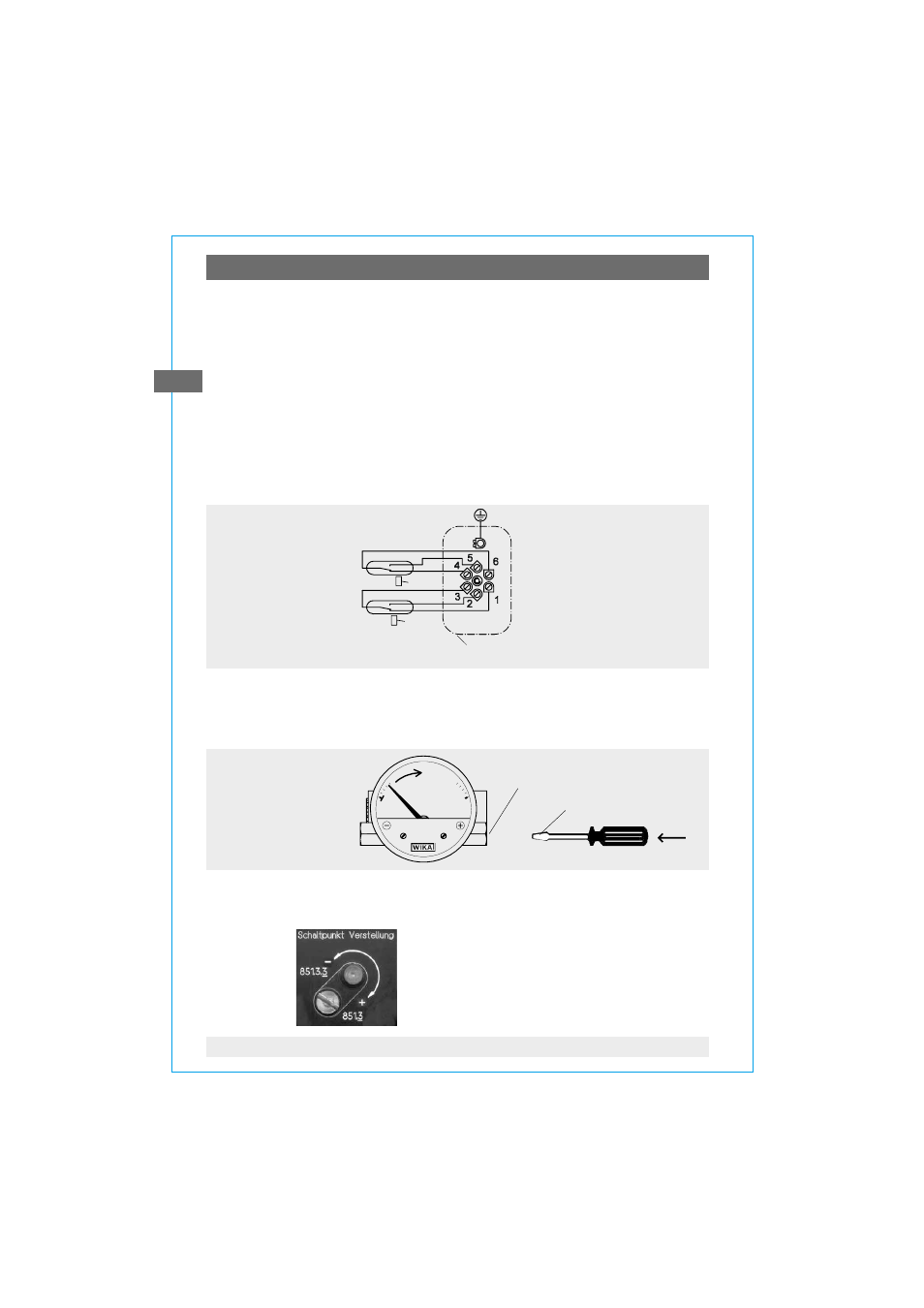
Wiring scheme
Reed contact
Model 851.3 and 851.3.3
851.3. 3 2nd contact
851. 3
1st contact
Terminal box
The gauges do not
provide for incorporated
overcurrent protectors.
If overcurrent protectors
are requested, these have
to be provided
for externally.
6.3 Setting the switching point
Preference should be given to setting the switching point before installing the
measuring instrument. The necessary test path is generated by hand (for
example, by means of a antimagnetic screw driver).
Manual generation
of test:
Plus measuring
media chamber
antimagnetic
The switching point can be set after installation even when under pressure.
The switching point is set by turning the contact setscrew on the outside of the
reed case.
By turning anti clockwise:
switching point moves in the direction
of the start of the measuring range
By turning clockwise:
the switching point moves towards the end
of the measuring range
Attention: The instrument is to be included in the equipotential bonding of the plant!