Commissioning, operation – WIKA WUR-1 User Manual
Page 13
GB
WIKA operating instructions attachable indicator, models A-AS-1, WUR-1
13
2437704.05 10/2012 GB/D/F/E
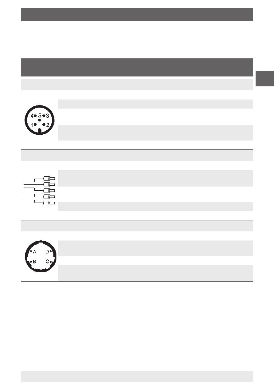
Output
2-wire
Current version
3-wire
Voltage version
Circular connector M12 x 1; 5-pin
1
Power supply U
B+
, Sig
+
Power supply U
B+
2
Switching output, out1
Switching output, out1
3
Power supply 0V, Sig-
Power supply 0V
Switching output ground, Sig-
4
Switching output ground
(potential-free)
Signal Sig
+
5
Switching output, out2
Switching output, out2
Cable outlet
red
Power supply U
B+
, Sig
+
Power supply U
B+
black
Power supply 0V, Sig-
Power supply 0V
Switching output ground, Sig-
yellow
Switching output ground
(potential-free)
Signal Sig
+
brown
Switching output, out1
Switching output, out1
orange
Switching output, out2
Switching output, out2
Bayonet connector; 4-pin
A
Power supply U
B+
, Sig+
Power supply U
B+
B
Switching output ground
(potential-free)
Signal Sig
+
C
Switching output, out1
Switching output, out1
D
Power supply 0V, Sig-
Power supply 0V
Switching output ground, Sig-
6. Commissioning, operation
Instrument connection (output)
Use the LED attachable indicator with shielded cable, and, if the lines are longer than
30 m or leave the building, earth the shield at least at one end of the cable.