6 wiring the tp line in/line out rj-45 connectors, Wiring the tp line in/line out rj-45 connectors, Figure 3: utp connector – Kramer Electronics TP-330FW User Manual
Page 9: Table 2: twisted pair cable wiring
Wiring the TP LINE IN/LINE OUT RJ-45 Connectors
7
7
On both TP-330FW units:
The ON LEDs light green indicating that they are receiving power
—and—
The CAT 5 LINK LEDs light green indicating that a CAT 5 link has been
established between the units
Notes:
•
You can connect two FireWire devices simultaneously to a TP-330FW,
however, only one device can be active at a time
•
There is no need to install the Kramer PT-1FW DV Line Protector on the
STP/UTP as the TP-330FW already contains built-in line protection
•
You can connect devices with 1394b (FireWire 800) bilingual interfaces at
speeds of up to 400Mbps. The FireWire cable used must have a bilingual
connector on one side and a 1394a 6-pin connector on the other side
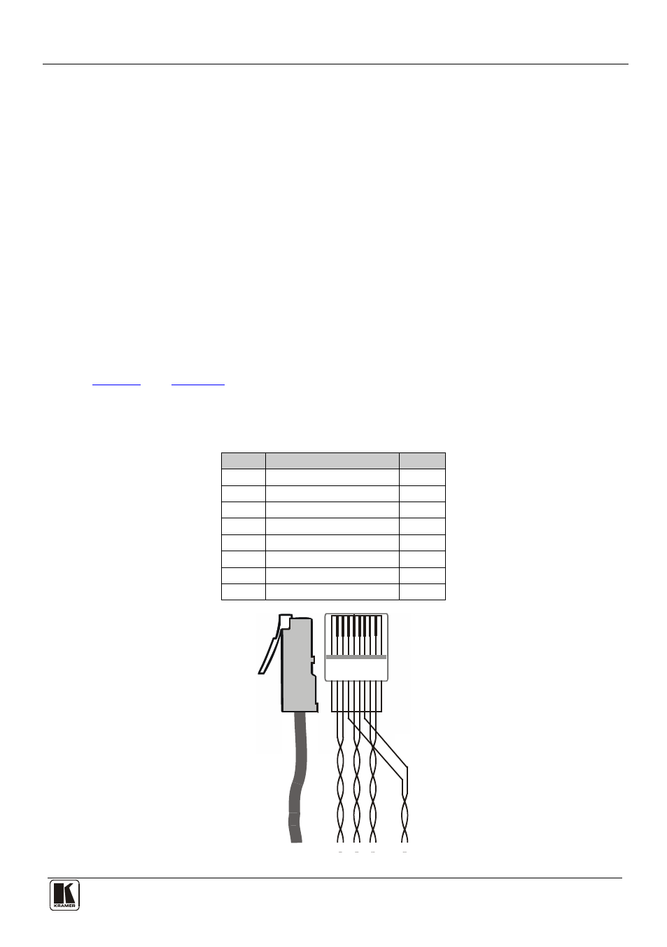
6 Wiring the TP LINE IN/LINE OUT RJ-45 Connectors
define the TP RJ-45 wiring that is different to the standard
EIA/TIA 568B wiring. When using STP cable, connect/solder the cable shield to
the RJ-45 connector shield.
Table 2: Twisted Pair Cable Wiring
PIN
Wire Color
PIN
1
Green/White
7
2
Green
8
3
Orange/White
3
4
Blue
4
5
Blue/White
5
6
Orange
6
7
Brown/White
1
8
Brown
2
36
78
12
5
4
1
45 78
6
3
2
Figure 3: UTP Connector