Wiring the cat 5 line in/line out rj-45 connectors, Figure 6: cat 5 pinout, Table 3: cat 5 pinout – Kramer Electronics 714 User Manual
Page 11: Table 3: cat 5 pinout figure 6: cat 5 pinout
Connecting the 713 and 714
9
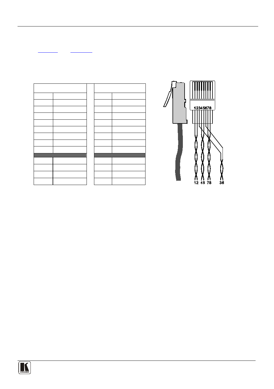
5.2 Wiring the CAT 5 LINE IN/LINE OUT RJ-45 Connectors
define the CAT 5 pinout, using a straight pin-to-pin cable
with RJ-45 connectors. When using STP cable, connect/solder the cable shield to
the connector shield.
Table 3: CAT 5 PINOUT
Figure 6: CAT 5 PINOUT
EIA /TIA 568A
EIA /TIA 568B
PIN
Wire Color
PIN
Wire Color
1
Green / White
1
Orange / White
2
Green
2
Orange
3
Orange / White
3
Green / White
4
Blue
4
Blue
5
Blue / White
5
Blue / White
6
Orange
6
Green
7
Brown / White
7
Brown / White
8
Brown
8
Brown
Pair 1
4 and 5
Pair 1 4 and 5
Pair 2 3 and 6
Pair 2 1 and 2
Pair 3
1 and 2
Pair 3 3 and 6
Pair 4
7 and 8
Pair 4 7 and 8
This manual is related to the following products: