5using your analog video to sdi converter, Using your analog video to sdi converter – Kramer Electronics FC-7501 User Manual
Page 6
KRAMER: SIMPLE CREATIVE TECHNOLOGY
Using Your Analog Video to SDI Converter
4
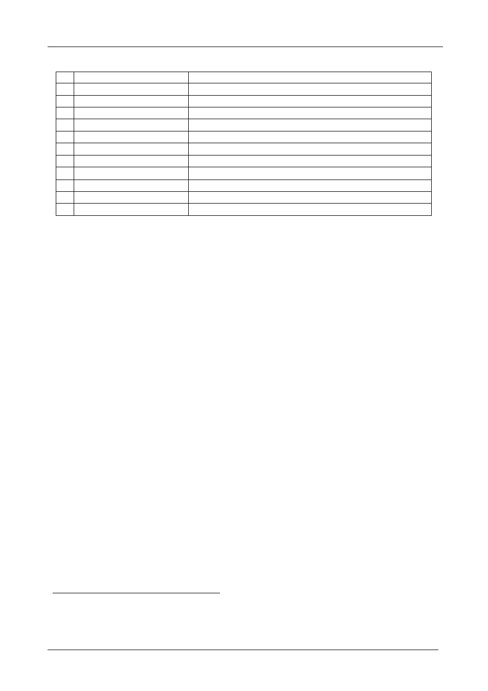
Table 2: Rear Panel FC-7501 Analog Video to SDI Converter
#
Feature
Function
5
CV/Y LOOP
BNC
Connector
Connects to the composite, s-Video
1
or component
2
video loop
6
B-Y LOOP
BNC
Connector
Connects to the component
2
video loop
7
C/R-Y LOOP
BNC
Connector
Connects to the s-Video
1
or component
2
video loop
8
SDI OUT 2
BNC
Connector
Connects to the serial digital video acceptor 2
9
CV/Y IN
BNC
Connector
Connects to the composite, s-Video
1
or component
2
video source
10
B-Y IN
BNC
Connector
Connects to the component
2
video source
11
C/R-Y IN
BNC
Connector
Connects to the s-Video
1
or component
2
video source
12 Hi-Z / 75
Button
Press to terminate at 75 or release for looping
3
13
SDI OUT 1
BNC
Connector
Connects to the serial digital video acceptor 1
14
RS-232
Port
Connects to the PC or the Remote Controller
15
12V DC
Power Connector VDC, 320mA
5
Using Your Analog Video to SDI Converter
You can use your
FC-7501, to convert professional quality composite
video, s-Video or component video (as the example in Figure 2 illustrates)
to one or two SDI video outputs.
To convert component video to two SDI video outputs, do the following:
1. Connect a component video source (for example, a Betacam component
VCR) to the component video BNC input connectors, Y, B-Y, and R-Y.
2. Connect both SDI outputs to SDI acceptors as follows (when only one SDI
output is required, use either of the SDI outputs of the
FC-7501, and leave
the other SDI output unconnected):
Connect the SDI OUT 1 BNC connector to an SDI acceptor
(for example, a Non-Linear Editor)
Connect the SDI OUT 2 BNC connector to the second SDI
acceptor (for example, an SDI monitor)
3. Connect the component video loop connectors, LOOP Y, LOOP B-Y,
and LOOP R-Y, to a component monitor, and release the Hi-Z/75
button to Hi-Z (optional).
When the inputs are not looped, the Hi-Z/75 button should be pressed
4. Connect the 12V DC power adapter to the power socket and connect the
adapter to the mains electricity.
1 For s-Video, connect the CV/Y and the C/R-Y connectors
2 For component video, connect all 3 connectors: Y, B-Y, and R-Y
3 Push in to terminate the input. Release when the input extends to another unit