3 setting the dip-switches, Setting the dip-switches, Table 2: setting the dip-switches – Kramer Electronics 7408 User Manual
Page 9: Descri
Using Your 7408 SDI to Analog Converter
7
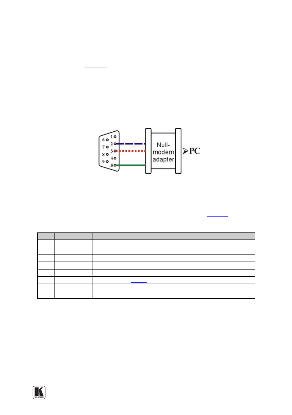
Hardware flow control is not required for this unit. In the rare case where a
controller requires hardware flow control, short pin 1 to 7 and 8, and pin 4
to 6 on the controller side.
Method B (
)—Connect the RS-232 9-pin D-sub port on the unit via
a straight (flat) cable to the null-modem adapter, and connect the null-
modem adapter to the RS-232 9-pin D-sub port on the PC. The straight
cable usually contains all nine wires for a full connection of the D-sub
connector. Because the null-modem adapter (which already includes the
flow control jumpering described in Method A above) only requires pins 2,
3 and 5 to be connected, you are free to decide whether to connect only
these 3 pins or all 9 pins.
Figure 4: Straight Cable RS-232 Connection with a Null-Modem Adapter
5.3
Setting the DIP-Switches
Configure the 7408 unit by setting the DIP-switches, as
defines:
Table 2: Setting the DIP-switches
DIPS
Function
Description
1
PROGRAM
ON for upgrading firmware; otherwise OFF
2
VBI
ON to enable Vertical Interval Blanking; OFF to disable
3 PEDESTAL
ON for pedestal (7.5 IRE offset selection for NTSC); OFF for no pedestal
4 4XOS
ON to enable oversampling
; OFF to disable oversampling
5
NTSC
)
6
PAL
ON for PAL (see
7
AUTO
ON for multi-standard; OFF for user selected (fixed) standard (see
)
8
COMPONENT ON for component video; OFF for composite video and/or s-video
1 NTSC offsets the black level within the active video signal by 7.5 IRE when selected
2 4xOS is 4 x Oversample
3 When this method is used, the noise figure is improved