Communication protocol (ver 0.1), Table 5: structure of the protocol, Table 6: instruction set for the 7408 – Kramer Electronics 7408 User Manual
Page 11: 7communication protocol (ver 0.1)
Communication Protocol (Ver 0.1)
9
7
Communication Protocol (Ver 0.1)
RS-232 communication between the 7408 and the PC is done using the following protocol. The protocol uses four bytes of
information, and data is at 9600 baud, no parity, 8 data bits and 1 stop bit. The controller and machine should be connected
via a null-modem connection, that is, if using a DB-9 port, connect as follows:
Connect pin 5 of the PC to pin 5 of the machine
Cross pins 2 and 3, i.e., connect pin 2 of the PC to pin 3 of the machine, and connect pin 3 of the PC to pin 2 of the machine
On the PC side, short pins 4 and 6
On the PC side, short pins 1, 7 and 8
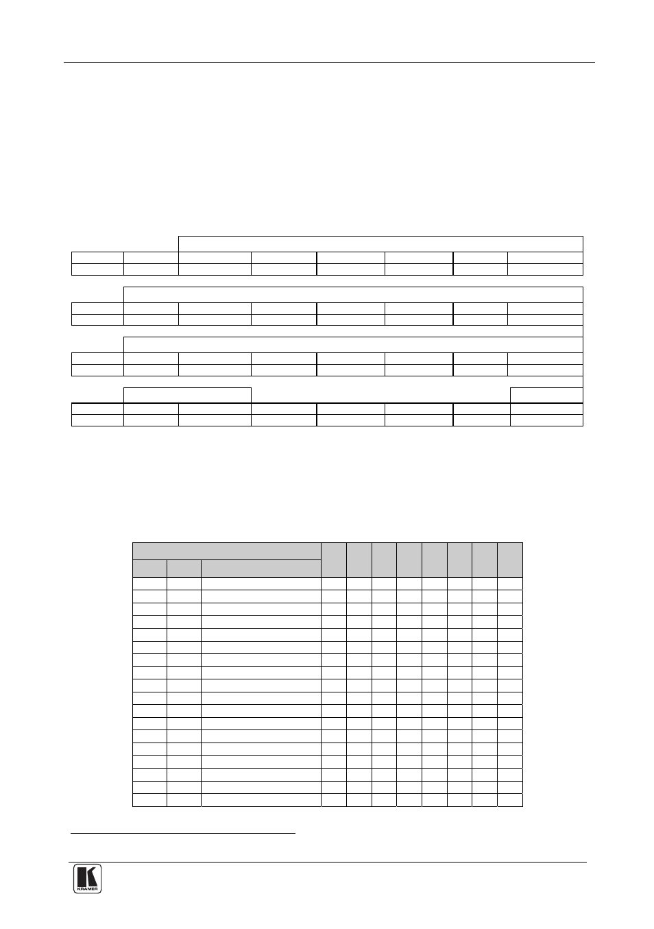
Table 5: Structure of the Protocol
MSB
LSB
INSTRUCTION
0
TO
PC
I5 I4 I3 I2 I1
I0
7
6
5 4 3 2 1
0
1st byte
DATA
1
D6
D5 D4 D3 D2 D1
D0
7
6
5 4 3 2 1
0
2nd byte
EXTENDED DATA
1
E6
E5 E4 E3 E2 E1
E0
7
6
5 4 3 2 1
0
3rd byte
MSB’s
ADDR
1
E7
D7 0 1 1 1
0
7
6
5 4 3 2 1
0
4th byte
Note that the MSB’s of the DATA (D7) and the EXTENDED DATA (E7) are in the fourth byte. Terminology:
TO PC is the “DESTINATION BIT”
I4..I0 is the “INSTRUCTION”
D7..D0 is the “DATA”
E7..E0 is the “EXTENDED DATA”
The destination bit, TO PC, is 0 when sending from the PC to the machine, or 1 when sending from the machine to the PC.
Table 6: Instruction Set for the 7408
INSTRUCTION
I7
I6
I5
I4
I3
I2
I1
I0
Dec
Hex
0 0 Reset
0 0 0 0 0 0 0 0
3 3 Store
machine
settings 0 0 0 0 0 0 1 1
4 4 Recall
machine
settings 0 0 0 0 0 1 0 0
5 5 Set
Video
Parameter
0 0 0 0 0 1 0 1
6 6 Request
Video
Parameter
0 0 0 0 0 1 1 0
7 7 Read
video
encoder
data 0 0 0 0 0 1 1 1
8 8 Write
video
encoder
data 0 0 0 0 1 0 0 0
10 A Write
EEPROM
data
0 0 0 0 1 0 1 0
11 B Read
EEPROM
data
0 0 0 0 1 0 1 1
12 C Write
I²C
0 0 0 0 1 1 0 0
13 D Read
I²C
0 0 0 0 1 1 0 1
14 E Read
video
standard
0 0 0 0 1 1 1 0
15 F Is
setup
defined?
0 0 0 0 1 1 1 1
16 10 Error
0 0 0 1 0 0 0 0
30 1E Lock
Front
Panel
0 0 0 1 1 1 1 0
31 1F Request
Bar
0 0 0 1 1 1 1 1
57 39 Enable
“Power-down
save” 0 0 1 1 1 0 0 1
61 3D Identify
machine
0 0 1 1 1 1 0 1
1 Note that the MSB’s of the DATA (D7) and the EXTENDED DATA (E7) are in the fourth byte