Kramer Electronics SL-10 User Manual
Page 9
6
SL-10 - Overview
#
Feature
Function
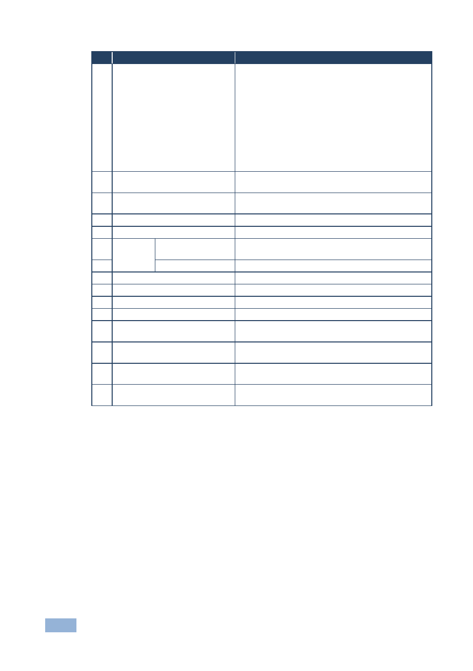
8
K-NET Connector
PIN GND is for the Ground connection; PIN B (-) and
PIN A (+) are for RS-485, and PIN +12V is for
powering other units
K-NET is a proprietary Kramer protocol for
interconnecting Kramer units
The ground connection is sometimes connected to the
shield of the RS-485 cable (in most applications, it is not
connected)
Note that the SL-10 cannot receive power via the K-NET
connector, but can power other units (but not another
SL-10)
9
RS-485 TERM Switch
Slides down for RS-485 termination, slides up for not
terminated
10
K-NET TERM Switch
Slides down for K-NET termination, slides up for not
terminated
11
PROG. Switch
For service use only
12
12V DC Socket
12V DC connector for powering the unit
13
IR
INPUTS
Built-in receiver and
STATUS LED
Accepts IR remote commands
14
3.5mm Mini Jack
Connects to an external IR receiver
15
RELAY LEDs
Illuminate when a relay is active (1 to 5)
16
IR LEDs
Illuminate when an IR port is active
17
NET LED
Illuminates when The Ethernet link is active
18
K-NET LED
Illuminates while transmitting over K-NET
19
RS-485 LED
Illuminates while transmitting/receiving on an RS-485
port
20
RS-232 (Tx/Rx) LEDs
Illuminate while transmitting/receiving on an RS-232
port (1 to 2)
21
GPI/O LEDS
Illuminate while transmitting/receiving on a general
purpose I/O port (1 to 2)
22
PROGRAM USB Connector
Connect to a computer for unit configuration and
firmware upgrading