Figure 2: rc-53dlc us version – rear panel, Table 2: rc-53dlc us version – rear panel features, Defining the rc-53dlc – Kramer Electronics RC-53DLC User Manual
Page 8
Defining the RC-53DLC
5
5
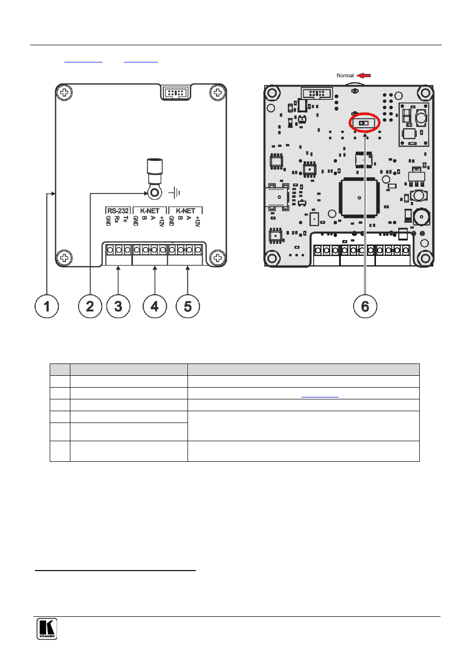
define the RC-53DLC rear panel.
Figure 2: RC-53DLC US Version – Rear Panel
Table 2: RC-53DLC US Version – Rear Panel Features
#
Feature
Function
1
Program USB Connector
Connect to a computer for firmware upgrade
1
2
Grounding Screw
Connect to grounding wire (see
Section
3
RS-232 Terminal Block
For factory use only
4
K-NET Terminal Block
Connect the GND to the Ground connection
2
, connect B (-) and
A (+) to RS-485, and connect +12V to +12V on the companion
unit
5
K-NET Terminal Block
6
PROG Switch
For technical support use only (should be set to the left in the
direction of the arrow for normal operation)
1 When the unit is connected via K-NET to a Master Room Controller, you can upgrade the firmware via the USB or ETH ports of the
Master Room Controller
2 The ground connection is sometimes connected to the shield of the RS-485 cable (in most applications, it is not connected)