Figure 11: rc-53dlc labels setup, Table 6: the commands configuration, As defined in table 6 – Kramer Electronics RC-53DLC User Manual
Page 15
KRAMER: SIMPLE CREATIVE TECHNOLOGY
Operating the RC-53DLC K-NET™ Auxiliary Control Panel
12
7
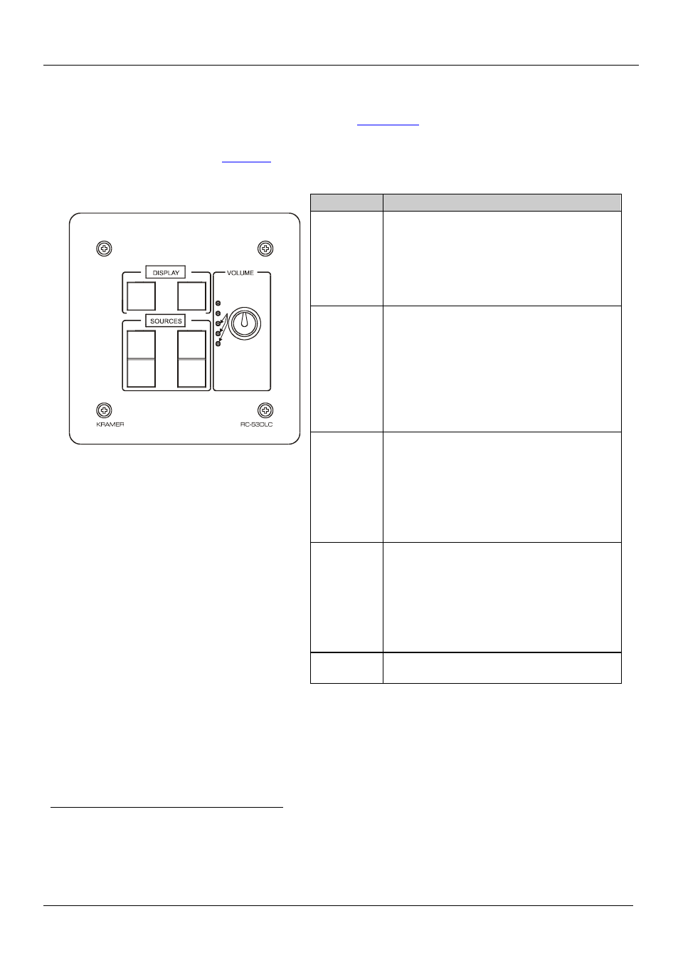
Operating the RC-53DLC K-
NET™ Auxiliary Control Panel
In the following example
1
), the auxiliary control panel is
labeled with specific functions and each button is programmed
2
to perform several
tasks
3
Table 6: The Commands Configuration
The Label
The Macro Sequence
Figure 11: RC-53DLC Labels Setup
ON
Power up the projector
Power up the DVD player
The DVD button turns blue
Roll down the projector screen
1 minute delay (for the projector to heat up)
The projector selects the DVD input
OFF
Power down the projector
Stop the DVD player
The DVD button turns red
Power down the DVD player
Stop the VCR
The VCR button turns red
Power down the VCR
Roll up the projector screen
DVD
Stop the video player
The VCR button turns red
The projector selects the DVD input
The DVD button color turns orange
Play the DVD
5 second delay
The DVD button color turns green
VCR
Stop the DVD
The DVD button turns red
The projector selects the VCR input
The VCR button color turns orange
Play the VCR
5 second delay
The VCR button color turns green
VOLUME
Use the VOLUME knob to adjust the audio
level
1 This is only one example among numerous possibilities, each button can be programmed as required. In this example, two buttons are
not assigned
2 By the technical installer
3 A macro sequence, including several commands per button, carried out one after the other