4 defining the rc-53dlc, 1 rc-53dlc for the us, Defining the rc-53dlc – Kramer Electronics RC-53DLC User Manual
Page 7: Rc-53dlc for the us, Figure 1: rc-53dlc us version – front panel, 4defining the rc-53dlc
KRAMER: SIMPLE CREATIVE TECHNOLOGY
Defining the RC-53DLC
4
4
Defining the RC-53DLC
This section defines the RC-53DLC US (see Section ) and |European versions.
4.1
RC-53DLC for the US
define the RC-53DLC front panel.
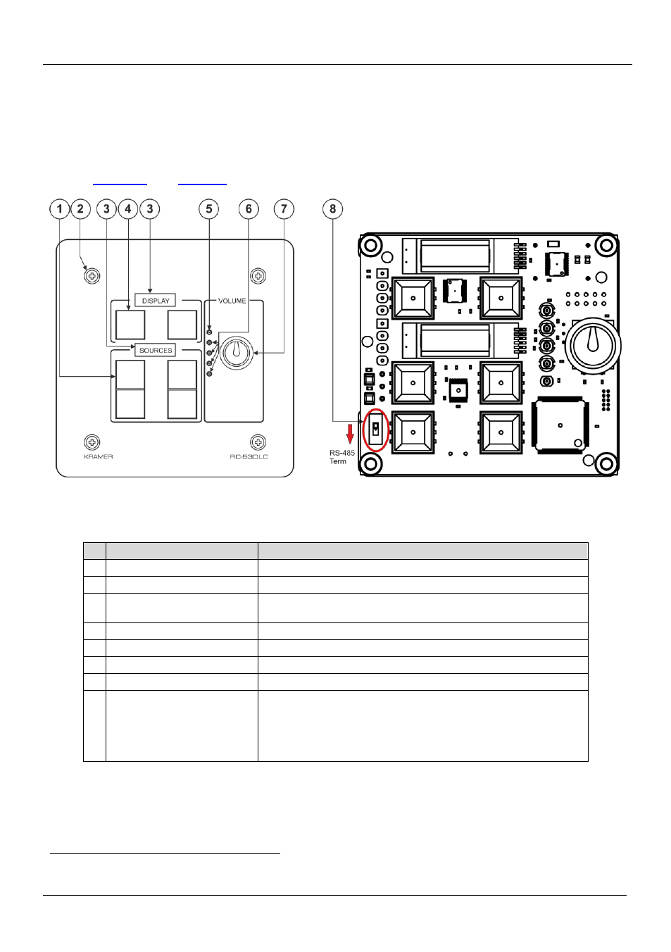
Figure 1: RC-53DLC US Version – Front Panel
Table 1: RC-53DLC K-NET™ Auxiliary Control Panel – Front Panel Features
#
Feature
Function
1
SOURCE Buttons
Group of four programmable, backlit buttons
1
2
Faceplate Screws
Four screws connecting the faceplate to the Rear Box
3
“DISPLAY” and “SOURCE”
Labels
Programmable, 8 character, LCD displays on a blue background
4
DISPLAY Buttons
Group of two programmable, backlit buttons
5
Maximum VOLUME LED
Lights red, indicating maximum volume
6
VOLUME LEDs
Light green, indicating volume level
7
VOLUME Knob
Rotate clockwise to increase volume level
8
K-NET TERM Switch
Slide downwards (in the direction of the arrow) for K-NET
termination, slide upwards to leave bus un-terminated.
The last physical device on a K-NET bus must be terminated
You can access the switch by removing the volume control knob, and
unscrewing the 4 screws on the front panel
1 By the system integrator only