Chemglass Jacketed Filter Reactors User Manual
Page 4
www.cglifesciences.com
Stirrer Shaft and Agitator Assembly
The stirrer shaft and agitators are assembled and installed when shipped. Use the following
instructions should you need to remove or adjust these components.
Components Needed for Stirrer Shaft and Agitator Assembly:
1ea CG-2097 Stirrer Shaft
1ea CG-2093 Flake Retaining Cup
1ea CG-2095 Upper PTFE Agitator
1ea CG-2096 Lower High Viscosity PTFE Agitator
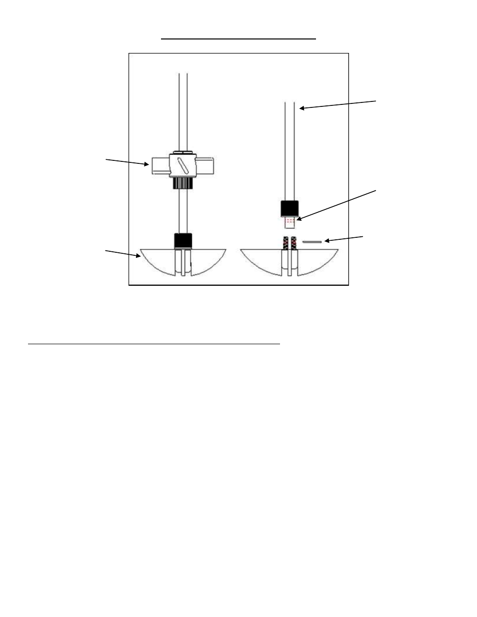
1. The lower agitator assembly (CG-2096) is placed on the end of the stirrer shaft aligning the
hole on the stirrer shaft with the holes in the PTFE hub. The sand blasted portion is the lower end
of the stirrer shaft. Insert the glass filled PTFE pin. The pin must be cut to 24mm long before
installing. Tighten the compression fitting. PLEASE NOTE: THE PTFE PIN MUST BE INSTALLED BEFORE
USING.
2. The upper agitator assembly (CG-2095) slides over the end of the shaft. The height from the
bottom will depend on the total volume you intend to run in the reactor.
3. Once you have the upper agitator in place, tighten the compression fitting as tight as possible
(by hand). For use at higher temperatures, Chemglass recommends heating the upper
agitator hub with a heat gun and then retightening. Then tighten the set screw on the flat of
the stirrer shaft using a screwdriver. This will minimize the possibility of the agitator falling or
slipping at higher temperatures.
4. The PTFE flake retaining cup (CG-2093) slides over the top of the stirrer shaft and is positioned
approximately 18 inches from the bottom of the lower agitator assembly (CG-2096). For the
cup to work effectively, the final position will have to be adjusted so that it is not less than 1
inch away from the bottom of the PTFE stirrer bearing.
CG-2095
Upper Agitator
CG-2096
Lower Agitator
CG-2097
Stirrer Shaft
Hole through the
Lower Portion of the
Stirrer Shaft
Glass Filled PTFE Pin
(MUST BE CUT TO
LENGTH BEFORE
INSTALLING)