Electrical-accessories, Warning, Vr 1 vr2 – Comfort-Aire HWW120 User Manual
Page 16: Accessory connections
15
Installation & Operation
WATER-TO-WATER (HWW) SERIES
Heat Controller, Inc.
Electrical-Accessories
Accessory Connections
A terminal paralleling the compressor contactor coil has been
provided on the CXM control of the HWW line. “A” has been
provided to control accessory devices, such as water valves,
electronic air cleaners, humidifiers, etc. Note: This terminal
must be used only with 24 Volt signals and not line voltage
signals. This signal operates with the compressor contactor.
See the wiring schematic for details.
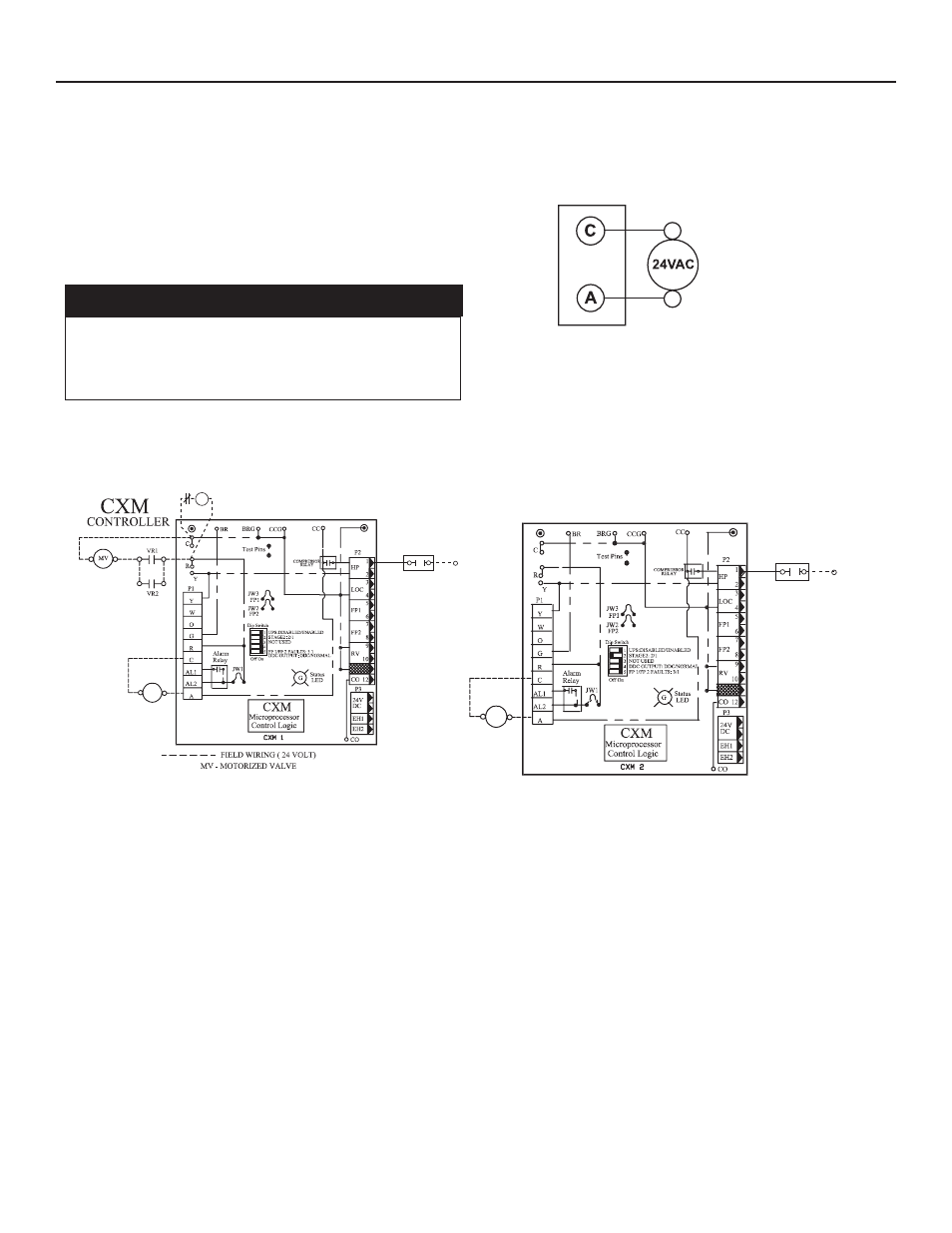
Figure 6: Field Wiring of 24 Volt Motorized Valve of Units Size 120
Coil
Coil
VR 1
VR2
6
8
Refrigerant
HP Switch
Circuit #1
VR3
NO
RED
RED
2
4
Refrigerant
HP Switch
Circuit #2
VR3
NO
RED
RED
6
8
Refrigerant
HP Switch
Circuit #1
VR3
NO
RED
RED
2
4
Refrigerant
HP Switch
Circuit #2
VR3
NO
RED
RED
Coil
Valve
Relay 3
Water
High Pressure
Switch NC
Coil
Valve
Relay 3
Water
High Pressure
Switch NC
Notes - Disconnect red wire at refrigerant HP switch connect to N.O. contact,
connect new red wire from N.O. contact to refrigerant HP switch.
Valve Relay 1, 2 - 13B0001N01 (SPDT) VR1, VR2
Valve Relay 3 - 13B0004N01 (DPDT) VR3
Coil
Coil
VR 1
VR2
6
8
Refrigerant
HP Switch
Circuit #1
VR3
NO
RED
RED
2
4
Refrigerant
HP Switch
Circuit #2
VR3
NO
RED
RED
6
8
Refrigerant
HP Switch
Circuit #1
VR3
NO
RED
RED
2
4
Refrigerant
HP Switch
Circuit #2
VR3
NO
RED
RED
Coil
Valve
Relay 3
Water
High Pressure
Switch NC
Coil
Valve
Relay 3
Water
High Pressure
Switch NC
Notes - Disconnect red wire at refrigerant HP switch connect to N.O. contact,
connect new red wire from N.O. contact to refrigerant HP switch.
Valve Relay 1, 2 - 13B0001N01 (SPDT) VR1, VR2
Valve Relay 3 - 13B0004N01 (DPDT) VR3
24 Volt Accessory Wiring for Units Size 036 and 060
These terminals may be
used to power 24 volt
water valves on units
size 036, 060
CXM Terminal Strip
Never jumper terminal “A” from CXM board #1 to CXM
board #2 on multi-compressor/control bound units. See
Figure 6 in electrical section of this document for motor-
ized valve wiring.
� WARNING! �