Electrical-line voltage, Caution, Warning – Comfort-Aire HWW120 User Manual
Page 15: Hww electrical data
14
Heat Controller, Inc.
WATER-TO-WATER (HWW) SERIES
Installation & Operation
Electrical-Line Voltage
HWW Electrical Data
General Line Voltage Wiring
Be sure the available power is the same voltage and phase as
that shown on the unit serial plate. Line and low voltage wiring
must be done in accordance with local codes or the National
Electric Code, whichever is applicable.
HWW Power Connection
Line voltage connection is made by connecting the incoming
line voltage wires to L1, L2, and L3 on power distribution
block. Consult electrical data table for correct fuse size.
208 Volt Operation
All 208-230 Volt units are factory wired for 208 Volt. The
transformers may be switched to 230V operation as illustrated
on the wiring diagram by switching the Red (208V) and the
Orange (230V) at the contactor terminal L2.
All field installed wiring, including electrical ground, must
comply with the National Electrical Code as well as all
applicable local codes.
Refer to the unit wiring diagrams for fuse sizes and a
schematic of the field connections which must be made by the
installing (or electrical) contractor.
Consult the unit wiring diagram located on the inside of the
compressor access panel to ensure proper electrical hookup.
All final electrical connections must be made with a length of
flexible conduit to minimize vibration and sound transmission
to the building.
� CAUTION! �
Use only copper conductors for field installed electrical
wiring. Unit terminals are not designed to accept other
types of conductors.
� WARNING! �
To avoid possible injury or death due to electrical shock,
open the power supply disconnect switch and secure it in
an open position during installation.
� WARNING! �
Disconnect electrical power source to prevent injury or
death from electrical shock.
Thermostat Connections
The aquastat/thermostat should be wired directly to the CXM board
#1. Note: The HWW second stage is wired directly to the CXM #2.
Low Water Temperature Cutout - FP1
The CXM control allows the field selection of source fluid low tem-
perature cutout points. The factory setting of FP1 is set for water
(35°F [1.7°C]). In cold temperature applications jumper JW3 (FP1-
antifreeze 15°F [-9.4°C]) should be clipped as shown in Figure 4 to
change the setting to 10°F [-12.2°C], a more suitable temperature
when using antifreezes. Never clip JW3 prior to antifreeze being
added to the loop.
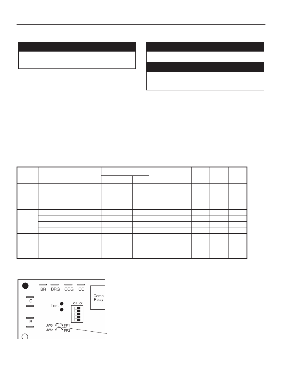
Figure 5: Changing FP1-Low Water Temperature Cutout Setpoint
CXM PCB
JW3-FP1
jumper
should be
clipped
when
antifreeze
is used.
Model
Voltage
Code
Voltage
Min/Max
Voltage
Compressor
HWG
Pump
FLA
EXT Loop
Pump
Fla
Total
Unit
FLA
Min
Circuit
Amps
Max
Fuse/
HACR
QTY
RLA
LRA
HWW036
1
208-230/60/1
187/254
1
16.7
79
0.4
4
16.7
20.8
35
3
208-230/60/3
187/254
1
10.4
73
-
-
10.4
13.1
20
4
460/60/3
414/506
1
5.8
38
-
-
5.8
7.2
15
5
575/60/3
518/633
1
3.8
36.5
-
-
3.8
4.7
15
HWW060
1
208-230/60/1
187/254
1
26.3
134
0.4
4
26.3
32.9
50
3
208-230/60/3
187/254
1
15.6
110
-
-
15.6
19.5
35
4
460/60/3
414/506
1
7.8
52
-
-
7.8
9.8
15
5
575/60/3
518/633
1
5.8
38.9
-
-
5.8
7.3
15
HWW120
1
208-230/60/1
187/254
2
26.3
134
0.4
4
52.6
59.2
80
3
208-230/60/3
187/254
2
15.8
110
-
-
31.2
35.1
50
4
460/60/3
414/506
2
7.8
52
-
-
15.6
17.6
25
5
575/60/3
518/633
2
5.8
38.9
-
-
11.6
13.1
15
HACR circuit breaker in USA only