Caution – Comfort-Aire FMG****X1E Series User Manual
Page 6
6
CAUTION:
This unit uses refrigerant R-410A. DO NOT use
any other refrigerant in this unit. Use of another
refrigerant will damage the unit.
• Every effort should be made by the installer to ensure
that the field installed refrigerant containing components
of the system have been installed in accordance with
these instructions and sound installation practices to
insure reliable system operation and longevity.
• Always refer to the installation instructions supplied with
the outdoor unit for piping requirements. The suction
and liquid lines must be sized in accordance with the
condensing unit specifications. See Figure 5 (page 12)
for liquid and suction line locations.
• When connecting refrigerant linesets together, it is
recommended that dry nitrogen be flowing through the
joints during brazing. This will prevent internal oxidation
and scaling from occurring.
• Refrigerant tubing should be routed in a manner that
minimizes the length of tubing and the number of bends
in the tubing. It should be supported in a manner that
prevents it from vibrating or abrading during system
operation. Tubing should be kept clean of foreign debris
during installation.
• If precise forming of refrigerant lines is required, a copper
tubing bender is recommended. Avoid sharp bends and
contact of the refrigerant lines with metal surfaces.
• Refrigerant lines should be wrapped with pressure
sensitive neoprene or other suitable material where
they pass against sharply edged sheet metal.
CAUTION:
Before brazing the FMG series air handler,
remove the core from the service port. Failure
to comply may result in leakage at the service
valve. Replace the core and cap once brazing
is complete.
• The FMG series air handler is charged through service
valves on the end of the liquid tube for each circuit.
These must be removed before brazing the line sets.
System Depressurization
1. Remove the cap from the end of the liquid line.
2. Verify pressurization by depressing the Schrader valve
on the end of the liquid line. Listen for any escaping gas.
If there is no pressure, test the unit for leakage.
• If leakage is found, clearly mark the location of the leak
and return the unit to the distributor for processing.
• If no leaks are found, the air handler may be installed.
3. Depress the valve to relieve all pressure from the coil.
Connecting the Linesets
NOTES: Before proceeding, perform steps 1 - 3 in the
System Depressurization section.
1. Route and cut both lineset tubes to proper length in
accordance with the outdoor unit specifications. Verify
the ends are round, clean, and free of any burrs.
2. Connect the suction and liquid lineset tubes.
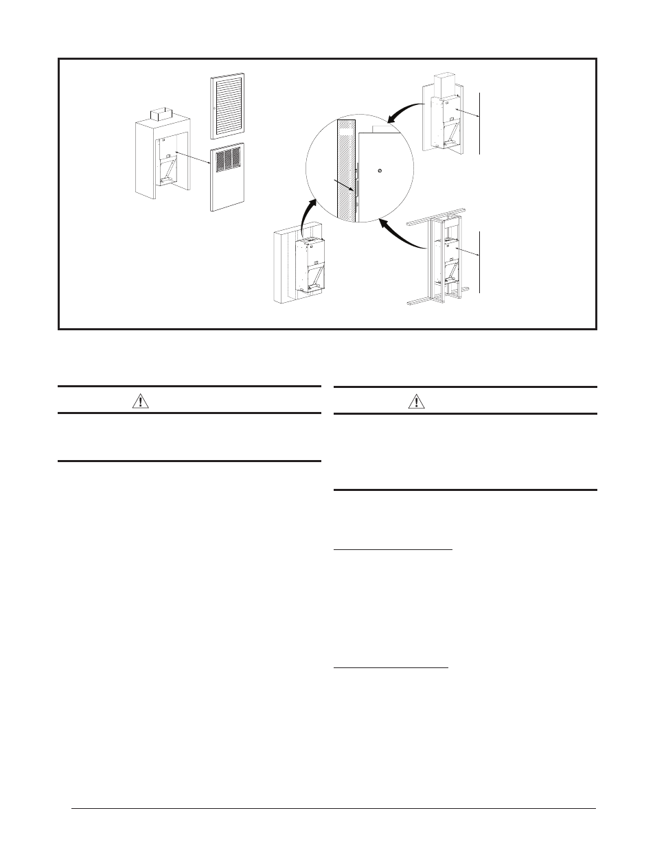
Figure 1. Unit Installation
18"
(457 mm)
24” Clearance from
nearest wall or
partition
Full Louvered
Door
Wall
Mount
Closet
Installation
Alcove
Installation
6”
(152mm)
Typical Closet Door
with Return Air Grill
Installed
OR
Recessed
Wall
Wall
2-Piece
Mounting
Bracket
24” Clearance from
nearest wall or
partition