Wiring dia gram – Comfort-Aire FMG****X1E Series User Manual
Page 15
15
NO
TES:
z
H0
6/
es
a
h
P
el
g
ni
S
tl
oV
04
2/
80
2
)
W
K0
1,
8(
M
C
E r
el
d
na
H r
i
A t
n
u
o
M ll
a
W
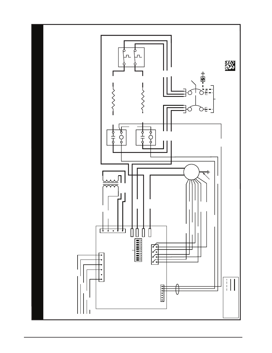
WIRING DIA
GRAM
FIELD
WIRIN
G
LEGEND
:
LO
W
VO
LT
AG
E
HIGH
VO
LT
AG
E
WIRING DIA
GRAM
1.
The blo
wer motor speed tap connection ma
y not be as
sho
wn.Refer to installation instructions pr
ovided with
unit to set DIP s
witches f
or the appr
opriate heating and
cooling speed setting f
or y
our application.
2.
Disconnect all po
wer bef
ore servicing.
3.
The transf
ormer ma
y ha
ve a dual v
oltage primary tap.
Match the tap position with the suppl
y
vo
ltage used.
4.
If the internal wiring is replaced,
use on
ly
105°C
copper wire of the same gaug
e.
711246
0
0812
Remar
ques
1.
Le connecteur de vitesse du moteur du ventilateur peut
différer de l’illustration.
Consultez les Instructions
d’installation.
2.
Débranchez toutes les sour
ces d’alimentation
av
ant l’entretien.
3.
Le transf
ormateur peut
av
oir un r
obinet principal à double
tension.
Agencez la position du r
obinet au type de tension de
l’installation.
4.
Si le câblage interne est remplacé,
utilisez seulement un fil de
cuivre 105° C du même gabarit
.
CONTR
OL
BO
ARD
R
C
L2
L1
L1
L1
L2
L2
Y
W
GC
R
CIRCUIT
BREAKER
TRANSFORMER
24V
208V
240V
ELEMENT RELA
Y
ELEMENT RELA
Y
ELEMENT
ELEMENT
SUPPL
Y
VO
LT
AG
E
ECM
MO
TO
R
HEA
TER
BLUE
ORANGE
LIMIT
2
1
4
3
COM
NO
COM
NO
GRA
Y
1
5
6
7
8
23
4
BLA
CK
BLUE
YELLO
W
ORANGE
RED
WHITE
BR
OW
N
YELLO
W/GREEN
HEA
T
OFF
ON
COOL
5 4 3 2 1 1 2 3 4 5
BLA
CK
WHITE
RED
BLA
CK
WHIT
E
GRA
Y
YELLO
W
WHIT
E
GRA
Y
RED
GREEN
BLA
CK
RED
RED
RED
BLA
CK
BLA
CK
BLA
CK
WHITE
HARNESS
RED
BLA
CK
GRAY
Figure 6. Wiring Diagram for 1.5, 2, 2.5, & 3 Ton Units