Wiring dia gram – Comfort-Aire FMG****X1E Series User Manual
Page 14
14
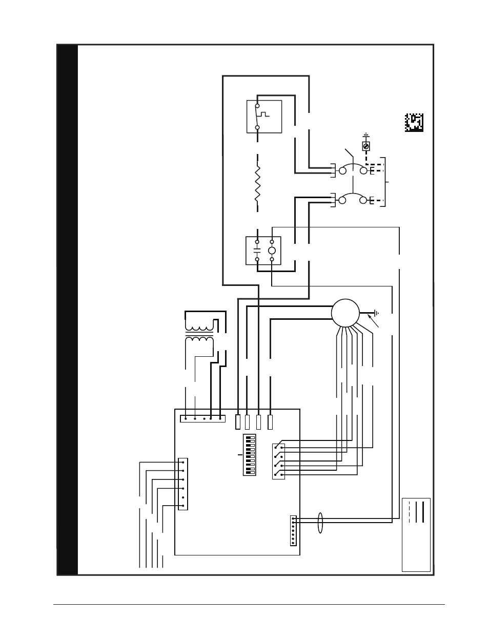
Figure 5. Wiring Diagram for 1.5, 2, 2.5, & 3 Ton Units
711245
0
1.
The blo
wer motor speed tap connection ma
y not be as
sho
wn.Refer to installation instructions pr
ovided with
unit to set DIP s
witches f
or the appr
opriate heating and
cooling speed setting f
or y
our application
.
NO
TES:
z
H0
6/
es
a
h
P
el
g
ni
S
tl
oV
04
2/
80
2
)
W
K5
(
M
C
E r
el
d
na
H r
i
A t
n
u
o
M ll
a
W
WIRING DIA
GRAM
FIELD
WIRIN
G
LEGEND
:
LO
W
VO
LT
AG
E
HIGH
VO
LT
AG
E
2.
Disconnect all po
wer bef
ore servicing.
3.
The transf
ormer ma
y ha
ve a dual v
oltage primary tap.
Match the tap position with the supp
ly
vo
ltage used.
4.
If the internal wiring is replaced,
use on
ly
105°C copper
wire of the same gaug
e.
WIRING DIA
GRAM
0812
Remar
ques
1.
Le connecteur de vitesse du moteur du ventilateur peut
différer de l’illustration
. Consultez les Instructions
d’installation.
2.
Débranchez toutes les sour
ces d’alimentation
av
ant
l’entretien.
3.
Le transf
ormateur peut
av
oir un r
obinet principal à
double tension.
Agencez la position du r
obinet au type
de tension de l’installation.
4.
Si le câblage interne est remplacé,
utilisez seulement un
fil de cuivre 105° C du même gabarit
.
CIRCUIT
BREAKER
LIMIT
ELEMENT REL
AY
ELEMENT
SUPPL
Y
VO
LT
AG
E
CONT
RO
L
BO
ARD
R
C
L2
L1
L1
L2
L2
Y
W
GC
R
TRANSFORMER
24V
208V
240V
ECM
MO
TO
R
HEA
TER
ORANGE
GRA
Y
COM
NO
L1
HEA
T
OFF
ON
COOL
1
5
6
7
8
23
4
BLA
CK
BLUE
YELLO
W
ORANGE
WHITE
BR
OW
N
WHITE
WHITE
YELLO
W/GREEN
5 4 3 2 1 1 2 3 4 5
BLA
CK
WHIT
E
BL
AC
K
WHIT
E
GRA
Y
YELLO
W
WHITE
GRA
Y
GREEN
RED
BLA
CK
BLA
CK
WHITE
RED
BLA
CK
HARNESS
RED