Rivera Primo Mid-Controls User Manual
Page 6
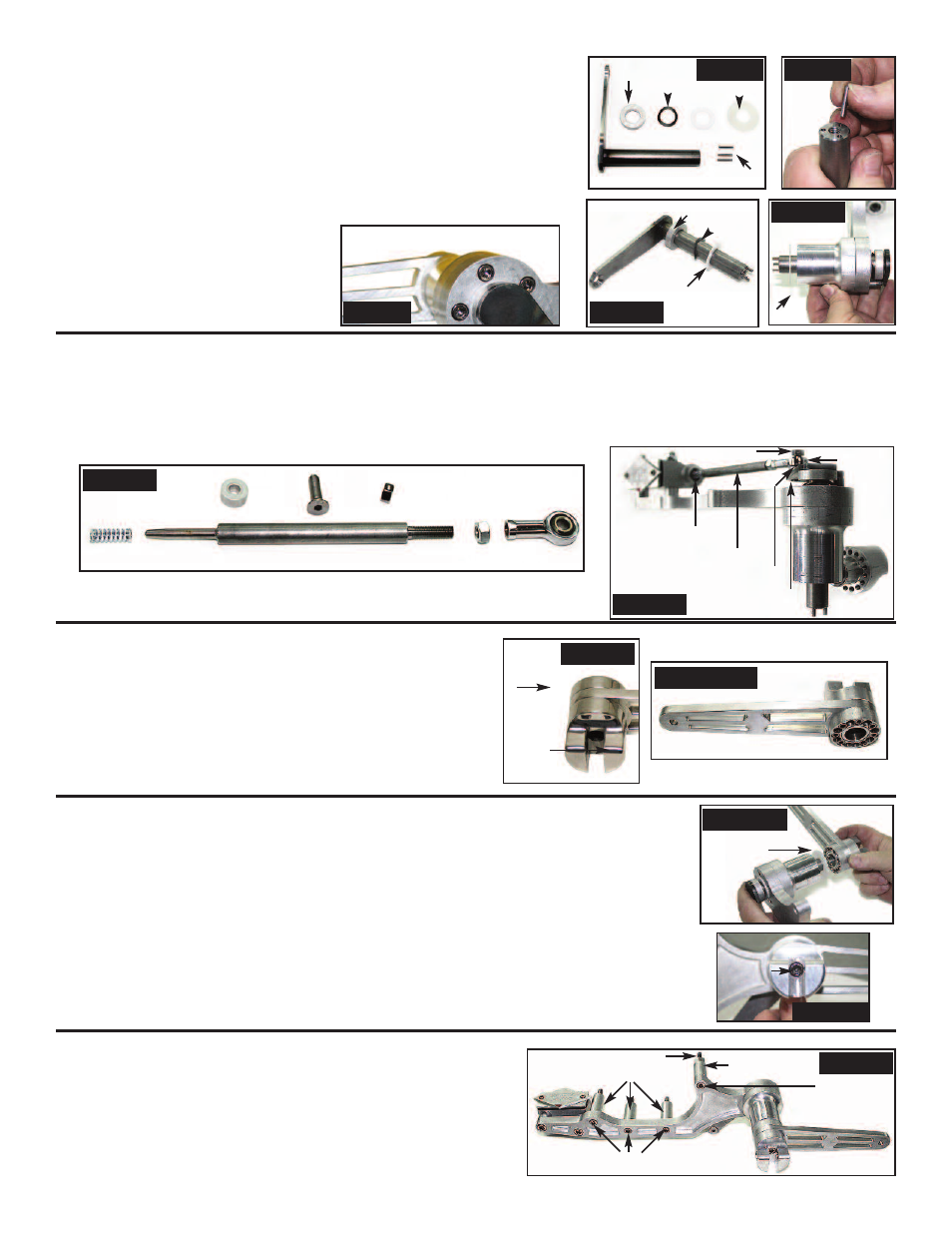
1. Install three(3) each pins (P/N 2101-0008) into the three holes on the threaed
end of welded brake linkage. Using a hammer tap the three pins until they
bottom out. (Photo 8 & 9)
2. Install spacer (P/N 2084-0075) onto welded brake linkage (flat side facing out).
Now install curved disc spring washer (P/N 1100-0018) followed by small
thrust washer (P/N 1101-0020). (Photo 10)
3. Install welded brake linkage (Photo 10) onto brake mounting plate with brake
pedal ext. and master cylinder from the master cylinder side. Now slide the
large thrust washer (P/N 1101-0022) onto welded brake linkage from the
outside. (Photo 11)
NOTE: NOTCH ON WELDED BRAKE
LINKAGE GOES BEHIND SHCS
(P/N 2100-0042) & SPACER
(P/N 2084-0071) ON BRAKE
MOUNTING PLATE. (Photo 7)
1. Install jam nut (P/N RIV-201) onto threaded end of of plunger rod (P/N 2084-0065) followed by rod end (P/N 2018-0099). (Photo 12)
2. Install 5/16-24 x 1.25” SFHCS (P/N 2100-0043) into welded brake linkage. On the other side install spacer (P/N 2084-0073).
(Photo 13)
3. Now install spring (P/N 1101-0023) on machined end of plunger rod (P/N 2084-0065). Guide the plunger rod & spring into the
master cylinder and install rod end onto P/N 2100-0043 followed by center locknut (P/N 2100-0044). (Photo 13)
4. Torque to 30 foot pounds.
1. Holding brake lever mounting block (P/N 2084-0055) so top front
is facing you, install brake lever (P/N 2084-0053) onto brake
mounting block lining up the top two mounting screw holes
(NOTE: THE BRAKE LEVER WILL POINT TO YOUR RIGHT).
(Photo 14)
2. Now install brake lever retainer (P/N 2084-0073) with counter-
bored holes facing outward. Start by installing 10-24 x1
-1/8
” SHCS
(P/N 2100-0048) in top hole and now install 10-24 x 1-
1/8
” SHCS
in every other hole going downwards and tighten. (Photo 15A/B)
1. Install brake lever with mounting block assembly onto welded brake linkage shaft that is installed
in brake mounting plate. The top hole on the brake mounting block will go in the top pin on brake
linkage shaft with thrust washer between the two.
2. Now tap the brake lever mounting block onto the welded brake linkage with a rubber hammer.
(Photo 16A)
3. Now install
5
/
16
-18 x 1” SHCS (P/N 2100-0047) thru center hole in brake lever mounting block
and thread onto welded brake linkage. (Photo 16B)
NOTE: YOU WILL USE THE
5
/
16
-18 x 1” SHCS TO PULL THE TWO UNITS TOGETHER
4. Now that the unit is complete remove
5
/
16
-18 x 1” SHCS and put one(1) drop of blue loctite
onto threads and torque to 30 foot pounds.
1. Install three(3) each
5
/
16
-18 x 3” SHCS (P/N 2100-0001) thru brake
mounting plate. Then slide three(3) each spacers (P/N 2084-0069)
onto
5
/
16
-18 x 3” SHCS.
2. Install one(1) each 5/16-18 x1” SHCS (P/N 2100-0047) into top hole
and thread round end of spacer (P/N 2084-0079) onto SHCS.
Thread 1/4-20 x 1.50” SSS into hex end of spacer (P/N 2100-0049).
Photo 8
Photo 9
Photo 10
Photo 11
Photo 12
Photo 13
Photo 15A/B
Photo 16A
Photo 16B
Photo 18
2084-0075
1100-0018
1100-0020
1101-0022
2101-0008
2084-0075
1100-0018
1100-0020
1100-0022
1101-0023
2084-0065
2084-0073
2100-0043
2100-0044
RIV-201
2018-0099
1101-0023
2018-0099
2084-0065
2084-0073
2100-0043
2100-0044
2084-0069
2100-0001
2084-0079
2100-0047
2100-0049
1101-0022
2100-0047
Retainer
Retaining
Block
Top Front
Photo 14
Photo 7