Mittler Bros Machine & Tool 400-202 User Manual
Page 4
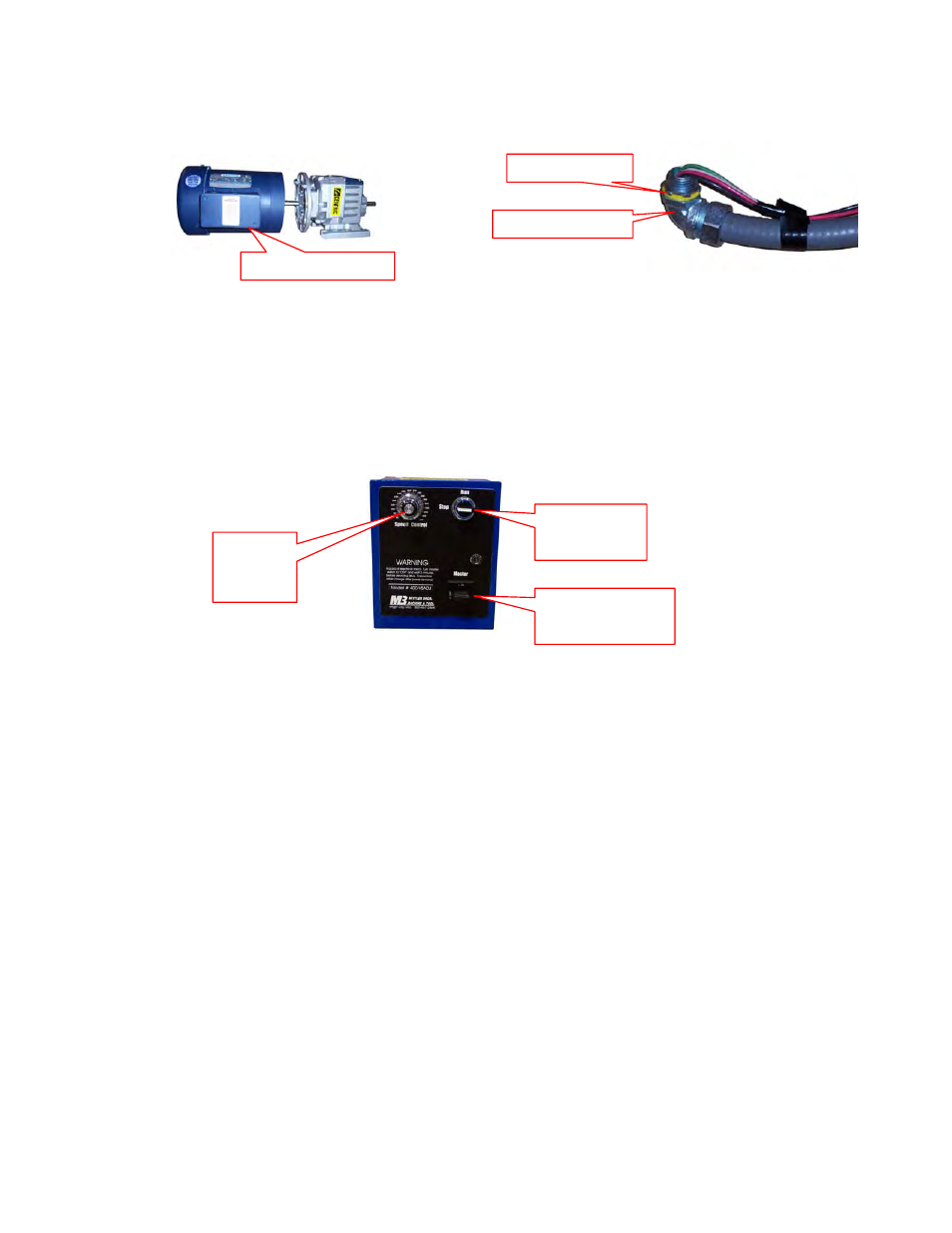
Conduit Nut
Conduit Elbow
Elbow Goes Here
15. Attach the conduit elbow to the bottom of box by removing the nut, slipping the fitting through and
then installing and tightening the nut.
16. Wire the control box to the motor as shown by the included wiring diagram. Use the supplied wire
nuts and then use electrical tape for added safety.
17. Wire the input cord correctly for the style and voltage you are using, refer to enclosed wiring
diagram.
Run Switch
STOP
Speed
Control
Knob
Master Switch
OFF
18. Check all bolts for tightness and all electrical connections. Once you are sure everything is tight
and correct set the master switch to OFF and the run switch to STOP. Plug the power cord into
the receptacle.
19. Turn the MASTER switch on and then turn the RUN switch on. Turn the speed control knob up
and down to cycle the motor. Listen for and clicking or odd sounds. If you here a clicking sound
you will need to loosen the spindle housing bolts and then retighten while the motor is running.
This will usually align the Love Joy and quiet the clicking.
KIT CONTENTS:
1ea. 400-503-M
Motor
1ea. 400-503-G Gear Box
1ea. 400-035 Large Love Joy Coupling Cover (guard)
1ea. 400-507 Love Joy Coupler Half 3/4” ID
1ea. 400-508 Love Joy Coupler Half 1” ID
1ea. 400-509 Love Joy Coupler Spider
1ea. 400-039 Control Box Mounting Plate
1ea. Pre Wired Speed Control Box
2ea. 5/16”-18 x 3/4” FHCS
4ea. 1/4”-20 x 1/2” SHCS
1ea. Wire
Diagram
1ea. Instruction
Sheet
Set
We appreciate your business and hope that you enjoy your new Mittler Bros. Product. If you have any
questions or concerns please feel free to call us at 1-800-467-2464 for help.