Nstallation – Glastender LC84 User Manual
Page 5
Glastender, Inc. • 5400 North Michigan Road • Saginaw, MI • 48604-9780
800.748.0423 • 989.752.4275 • Fax 800.838.0888 / 989.752.4444 • www.glastender.com
2
1. ELECTRICAL HOOKUP
• Unit is supplied with a 20-amp line cord on the left rear
of the unit.
• The main supply cord comes off the control box, located
on the pump deck. The refrigeration power cord plugs
into the back of the control box, also located on the pump
deck.
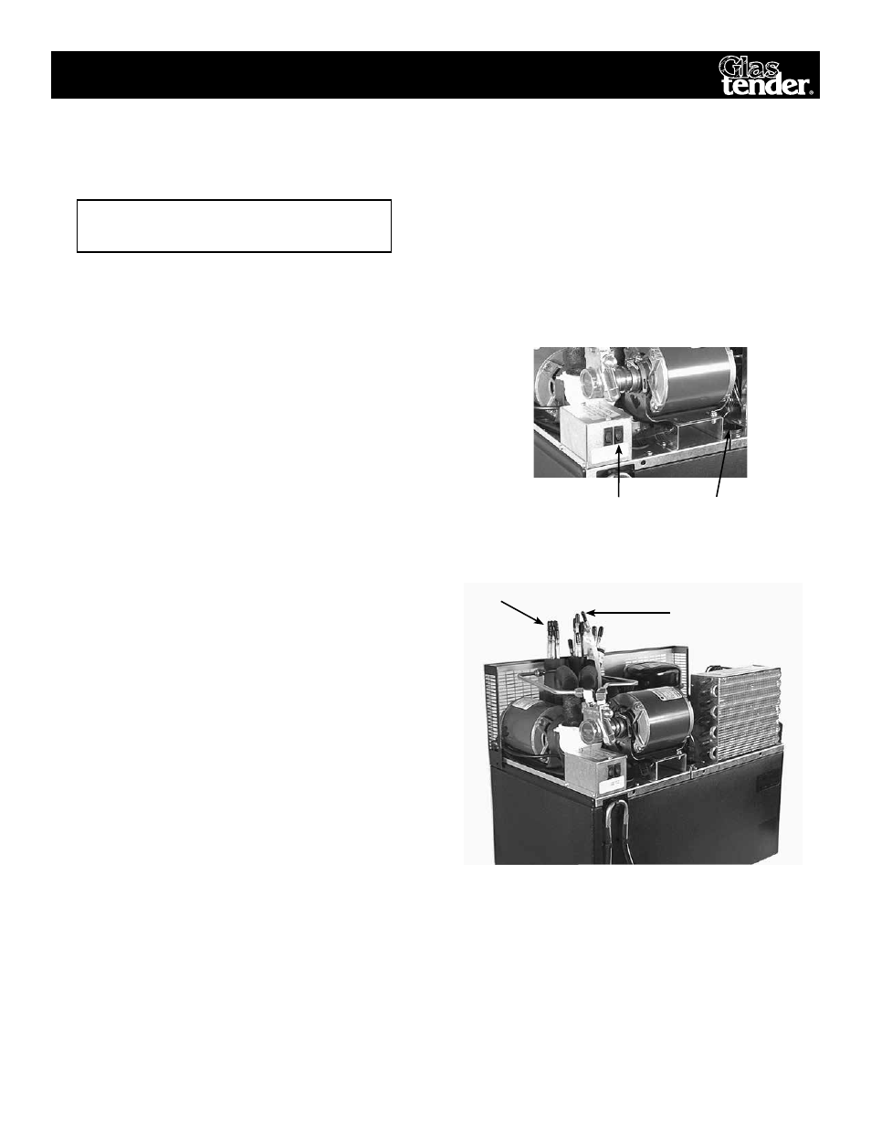
2. REFRIGERATION START-UP
• Remove top cover. Locate the black plastic water bath
fill-plug and remove it. (see fig.3)
• Fill the unit with clean water until water begins to come
out of the overflow tube.
• Plug in main power cord and the condenser fan and
compressor should start. (see fig. 3) If not, refer to
“TROUBLESHOOTING PROCEDURES”.
NOTE: A small amount of water will flow out of the over
flow tube until the ice is fully formed.
3. CONNECTION OF WATER SUPPLY
•
Glastender, Inc. recommends that a 1/2” water line with
shut-off valve be installed within 10-ft. (3 M.) of the unit.
Incoming water pressure is not to be less that 20 P.S.I.
NOTE: If water pressure exceeds 60 P.S.I. or severely fluc-
tuates, a water pressure regulator is required ahead of the
brass pump to avoid flooding the Carbonator. This regulator
is not supplied as standard equipment
• Before connecting water supply, drain approximately
two gallons of water from supply to flush out foreign
matter.
• It is recommended that a water filtering systems be
installed to reduce “off” tastes and odors. Use a system
that can filter out dirt particles 1 micron and larger.
Also amoebic and giardial cysts, asbestos fibers and
other similar contaminants.
• Connect water supply to the 3/8” barb of the fitting of
the water-in tube. (see fig. 4, Labeled Water Supply)
• Secure with proper sized “O” clamps.
4. CONNECTION OF “PRODUCT OUT” LINES
•
Install the insulated bundled tubes on the 3/8” barb fittings.
i
nstaLLation
Fig. 3
Control Box Switches
Filling the
Water Bath
Fig. 4 Connection of Water in Line
5. CONNECTION OF “PRODUCT IN” LINES
• Install the 1/4” I.D. braided tubing from the syrup
supply location to the 1/4” male barb connections on
the unit. Use tie wraps to neatly bundle supply lines.
• Secure lines to product coils with “O” clamps.
Water-in Tube
Syrup and Soda Lines
•
Connect syrup out lines (3/8” male barb) to a color-
coded conduit. (Note which numbered line goes to
which colored tube.) (see fig. 4)
• Secure connections with proper sized “O” clamps.
• Connect the recirculating soda line (3/8” tubing) to
the barbed fitting coming from the insulated pump.
(see fig. 4) Labeled “Soda Return”.
•
Connect the other 3/8” line to the barbed fitting on the
soda coil. Labeled “Soda Out”.
NOTE: THIS UNIT REQUIRES 20
AMP CIRCUIT PROTECTION