Goulds Pumps ChemBasePlu - IOM User Manual
Page 16
ChemBasePlus™ — 1/2002
Page
15 of 16
3) Negative Reading - The coupling halves
are further apart on the right side than the
left. Correct by either sliding the shaft end
of the driver to the left or the other end to
the right.
Positive Reading - The coupling halves
are closer together on the right side than
the left. Correct by either sliding the shaft
end of the driver to the right or the other
end
to the left (Fig. IV-3).
4) Repeat steps 1 through 3 until indicator A
reads .002 in. (.05 mm) or less.
5) Re-check both horizontal and vertical
readings to ensure adjustment of one did
not disturb the other. Correct as
necessary.
PARALLEL ALIGNMENT
A unit is in parallel alignment when indicator P
(parallel indicator) does not vary by more than
.002 in. (.05 mm) as measured at four points
90° apart at operating temperature. Note the
preliminary vertical cold setting criteria, Table
1.
Vertical Correction (Top-to-Bottom)
1. Zero indicator P at top dead center of
coupling (12 o’clock) half Y (Fig. III-1).
2. Rotate indicator to bottom dead center (6
o’clock). Observe needle and record
reading.
3.
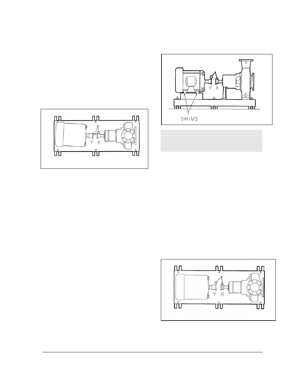
Negative Reading - Coupling half X is
lower than coupling half Y. Correct by
removing shims of thickness equal to half
of the indicator reading under each driver
foot.
Positive Reading - Coupling half X is
higher than coupling half Y. Correct by
adding shims of thickness equal to half of
the indicator reading from each driver foot
(Fig. IV-4).
NOTE: Equal amounts of shims must be
added to or removed from each driver foot.
Otherwise the vertical angular alignment will be
affected.
4.
Repeat steps 1 through 3 until indicator P
reads within .002 in. (.05 mm) or less when
hot, or per Table 1 when cold.
Horizontal Correction (Side-to-Side)
1. Zero indicator P on the left side of coupling
half Y, 90° from top dead center
(9 o’clock).
2. Rotate indicators through top dead center
to the right side, 180° from the start
(3 o’clock). Observe needle and record
reading.
3.
Negative Reading - Coupling half Y is to
the left of coupling half X. Correct by
sliding driver evenly in the appropriate
direction (Fig. IV-5).
Positive Reading - Coupling half Y is to
the right of coupling half X. Correct by
sliding driver evenly in the appropriate
direction.
NOTE: Failure to slide motor evenly will affect
horizontal angular correction.
4.
Repeat steps 1 through 3 until indicator P
reads .002 in. (.05 mm) or less.
5.
Re-check both horizontal and vertical
readings to ensure adjustment of one did
not disturb the other. Correct as
necessary.
Fig. IV-4
Fig. IV-3
Fig. IV-5