Appendix iv, Alignment – Goulds Pumps ChemBasePlu - IOM User Manual
Page 15
ChemBasePlus™ — 1/2002
Page
14 of 16
APPENDIX IV
Alignment
SET UP
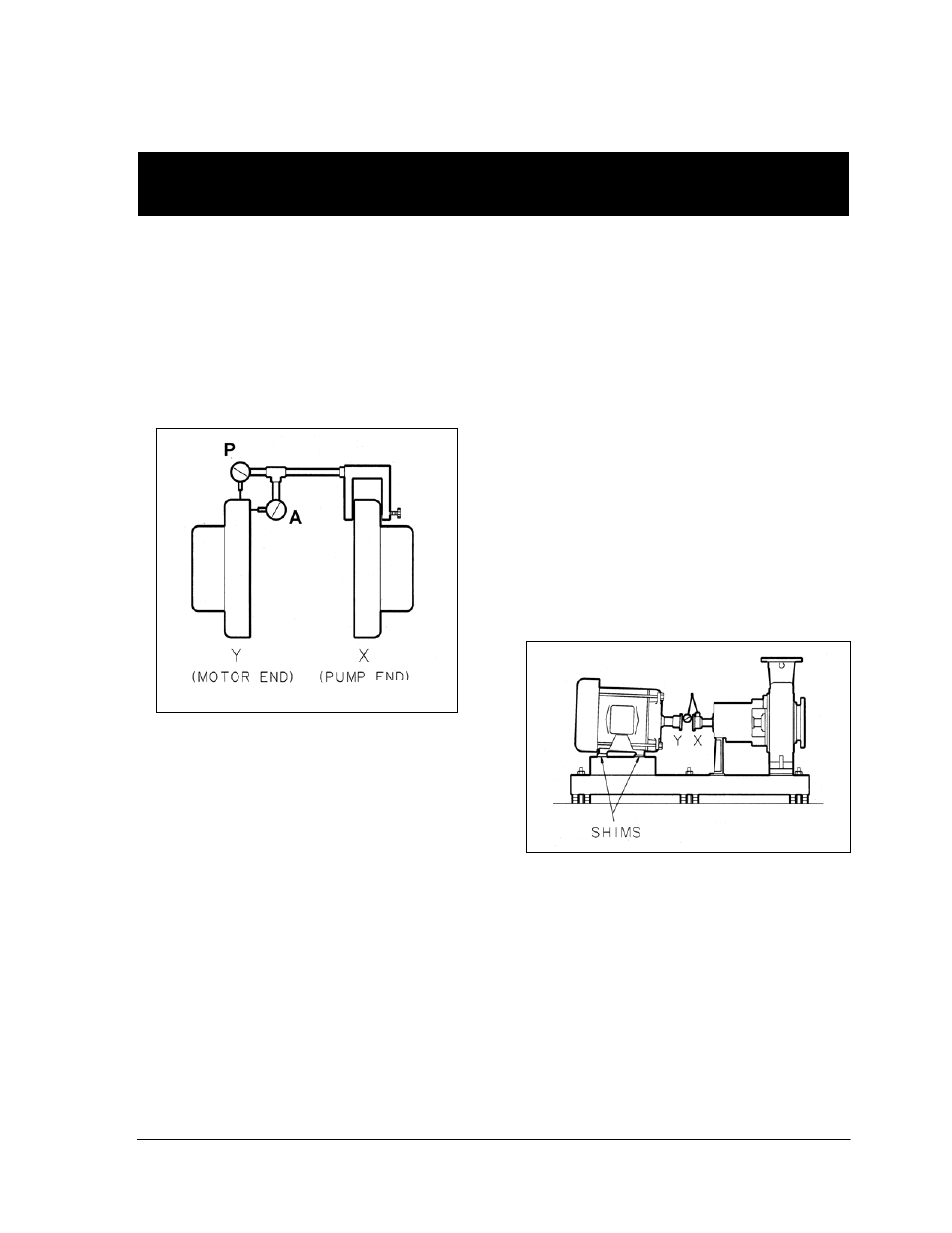
1.
Mount two dial indicators on one of the
coupling halves (X) so they contact the
other coupling half (Y) (Fig. IV-1).
2.
Check setting of indicators by rotating
coupling half X to ensure indicators stay in
contact with coupling half Y but do not
bottom out. Adjust indicators accordingly.
MEASUREMENT
1.
To ensure accuracy of indicator readings,
always rotate both coupling halves
together so indicators contact the same
point on coupling half Y. This will eliminate
any measurement problems due to runout
on coupling half Y.
2. Take indicator measurements with driver
feet hold-down bolts tightened. Loosen
hold down bolts prior to making alignment
corrections.
3. Take care not to damage indicators when
moving driver during alignment corrections.
ANGULAR ALIGNMENT
A unit is in angular alignment when indicator A
(Angular indicator) does not vary by more that
.002 in. (.05 mm) as measured at four points
90° apart.
Vertical Correction (Top-to-Bottom)
1. Zero indicator A at top dead center (12
o’clock) of coupling half Y.
2. Rotate indicators to bottom dead center (6
o’clock). Observe needle and record
reading.
3. Negative Reading - The coupling halves
are further apart at the bottom than at the
top. Correct by either raising the driver feet
at the shaft end (add shims) or lowering
the driver feet at the other end (remove
shims), (Fig. IV-2).
Positive Reading - The coupling halves
are closer at the bottom than at the top.
Correct by either lowering the driver feet at
the shaft end (remove shims) or raising the
driver feet at the other end (add shims).
4.
Repeat steps 1-3 until indicator A reads
.002 in (.05 mm) or less.
Horizontal Correction (Side-to-Side)
1. Zero indicator A on left side of coupling
half Y, 90° from top dead center
(9 o’clock).
2. Rotate indicators through top dead center
to the right side, 180° from the start
(3 o’clock). Observe needle and record
reading.
Fig. IV-2
Fig. IV-1