4" bore installation continued – ACE Controls 4" Bore Self-Compensating User Manual
Page 2
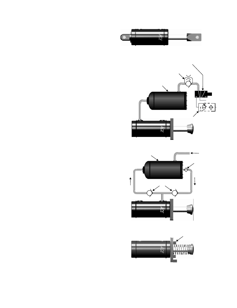
Figure 4
World leader in deceleration technology
ISO 9001:2000 Certified
ACE Controls Inc.
ACE Form24, 4” Bore Sel-Comp.
04/01/2004
CLEVIS MOUNTING INSTALLATION
Fasten the rear clevis and the rod clevis (Figure 4) to
the mating clevis members of the equipment. Make
sure the shock absorber is using the full stroke plus
.03 in (0.8 mm) and is not bottoming out. Be sure
that the equipment cannot pull the rod out any further
than the shock absorber stroke will allow.
AIR EXHAUST CIRCUIT FOR MODEL
CAA SHOCK ABSORBER
This type of installation (Figure 5) is necessary when
it is desired to have the rod remain in the shock
absorber after decelerating the load. Use special care
to avoid overfilling the air-oil tank. If not built in, a
special ACE check valve should be used to eliminate
“misting” of oil out of the air-oil tank.
RE-CIRCULATING COOLING CIRCUIT FOR MODELS
CAA & CSA SHOCK ABSORBERS
This type of installation (Figure 6) may be required when
ambient temperatures and/or cycle rates cause a self
0
contained shock to heat beyond 200 F. Use high pressure
(1,000 psi) check valves with a low cracking pressure
(5 psi). If a filter is to be used in this circuit, a 30 to 40
micron filter element with a 5 psi by-pass is recommended.
Consult factory for assistance.
PRIMARY MOUNTING INSTALLATIONS
Install the ACE self-compensating shock on a surface of
sufficient strength. Align the shock absorber rod end
button with the load striking surface and the bleed screws
and/or ports pointing up if mounted horizontally. Tighten
the (6) 5/8-18 UNF screws securely (Figure 7).
Figure 5
Optional Filter
(6) 5/8-18 UNF
Air Supply
Air-Oil Tank
Figure 6
Figure 7
Exhaust
Supply
Special ACE
Check Valve
Air-Oil Tank
Filter/Regulator
3-Normally
Closed Valve
Sol
High Pressure Check Valve