ACE Controls MVC 900 User Manual
Installation instructions, Stoplight proximity switches for use with
Installation Instructions
MA 150, 225, 600 & 900
SC 190, 300, 650 & 925
MC 150, 225 & 600
MVC 225, 600 & 900
TM
StopLight Proximity Switches For Use With. . .
Installation Instructions: Dimensions in inches (metric)
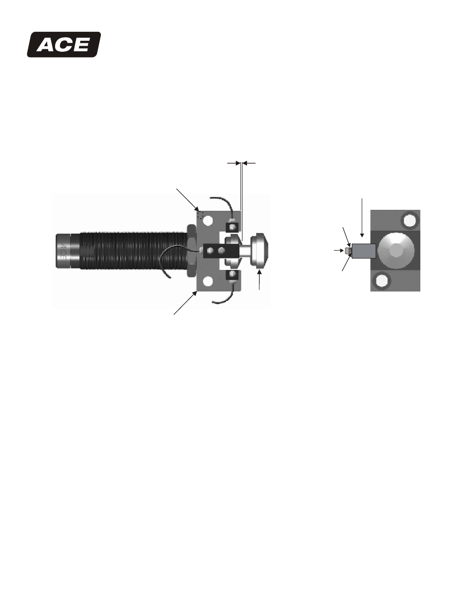
1. Install the rod button onto the shock absorber by pressing with hand force.
2. Screw the shock absorber into the mounting block and position according to the shock absorber
installation instructions. Use the front of the mounting block as a positive stop.
3. Tighten down the nylon tipped locking screw, in the side of the mounting block with a 5/64 (2 mm)
hex key. Tighten to 2.5 - 3.0 in lbs. (.28 - .34 Nm).
4. Position the proximity switch on the mounting block in any of the three positions and holding the
switch against the cut out surface, tighten the screw to 2.5 - 3.0 in lbs. (.28 - .34 Nm).
5. An additional washer is shipped with the MC 225M mounting block. It must be added to the screw
and washer assembly if position 2 is selected.
6. Make sure the wiring is done according to the diagram, before connecting the power.
7. Connect the ends of the wire as close as possible to the switch.
8. Do not install the lead wires parallel to an electrical or power line.
23435 Industrial Park Drive
Farmington Hills, Michigan 48335
tel: 248.476.0213
fax: 248.476.2470
www.acecontrols.com
Lock
Washer
Flat Washer
Screw
Proximity Switch
Nylon Tipped
Locking Screw
.05 (1.3 mm) Minimum
Sensing Distance
Position 1
Position 3
Position 2
Mounting Block
Rod Button
World leader in deceleration technology
ISO 9001:2000 Certified
ACE Controls Inc.