ACE Controls NA Adjustable 3" Bore Series User Manual
ACE Controls For the car
World leader in deceleration technology
ISO 9001:2000 Certified
ACE Controls Inc.
Installation Instructions
CA & CNA Self-Compensating and
A & NA Adjustable 2” & 3” Bore Series
23435 Industrial Park Drive
Farmington Hills, Michigan 48335
tel: 248.476.0213
fax: 248.476.2470
www.acecontrols.com
GENERAL
Install the ACE shock absorber on a surface of
sufficient strength. Align the shock absorber rod
end button with the load striking surface. This will
help to avoid side-loading. Use the full stroke of
the shock absorber up to the last .09 inch
(2.3 mm) and provide a solid mechanical stop to
prevent bottoming out.
Guard the shock absorber to protect it from
foreign materials such as acids, steam, weld flash,
solvents, cutting fluids, as well as dust and debris.
Mount in an area consistent with the operating
temperature range of the shock absorber, not to
0
0
exceed 75 F (24 C) ambient if cycled at full energy
capacity. To allow maximum heat dissipation, do not
paint the shock absorber. Applications using two
or more shock absorbers should have the load
balanced equally between them.
Note: Self-contained models CA, CNA, A and NA
models, are pre-filled with ATF and are ready for use
after proper installation.
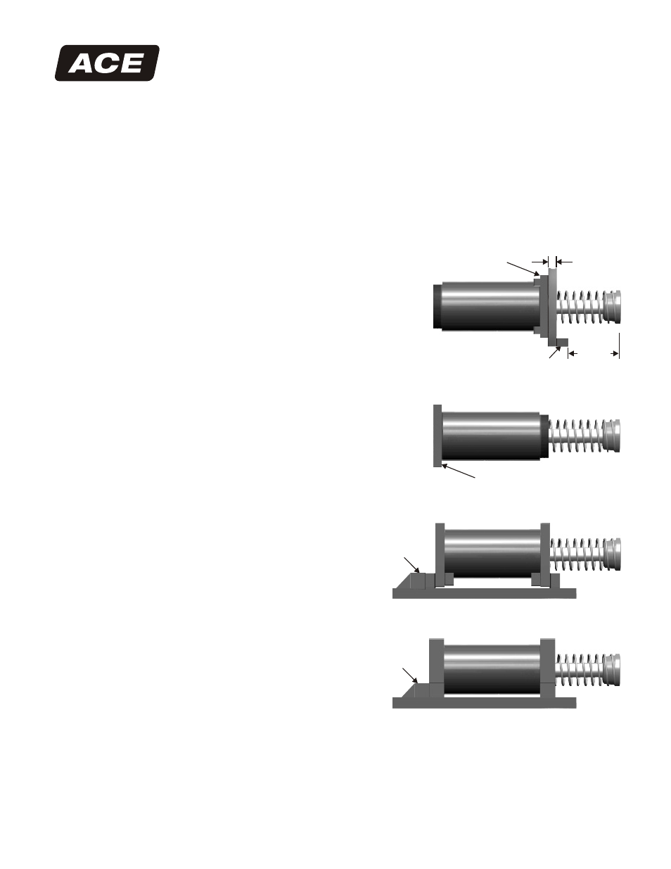
FRONT OR REAR FLANGE MOUNTING INSTALLATION
(Figures 1 & 2)
Install the ACE CA or A model shock absorber with
flange to a mounting structure of sufficient strength.
Assure that the bolts are securely tightened. See
comments above in General section concerning
addition of mechanical stop.
SIDE-FOOT MOUNT INSTALLATION (Figures 3 & 3A)
Bolt side-foot mount assembly to the mounting
structure. Assure that the bolts are securely tightened.
Four 5/8 inch (16 mm) bolts, grade 8 or higher, are
required. In order to prevent movement of the
side foot-mount assembly, weld a key into position
behind the rear foot bar.
Maximum efficiency of operation can be obtained by
carefully following these instructions:
Figure 1. . .Front Flange Mounting
Figure 3. . .2” Bore Side-Foot Mounting
Figure 3A. . .3” Bore Side-Foot Mounting
Figure 2. . .Rear Flange Mounting
Rear Flange
Front Flange
1.50 in
(38.1 mm)
Minimum
Solid Mechanical Stop
Welded
Key
Welded
Key
Nominal
Stroke
-0.9 in (2.3 mm)