Installation instructions – ACE Controls 1-1/2" Bore Adjustable User Manual
Page 2
World leader in deceleration technology
ISO 9001:2000 Certified
ACE Controls Inc.
ACE Form 23,1-1/2” Adjustable
04/01/2004
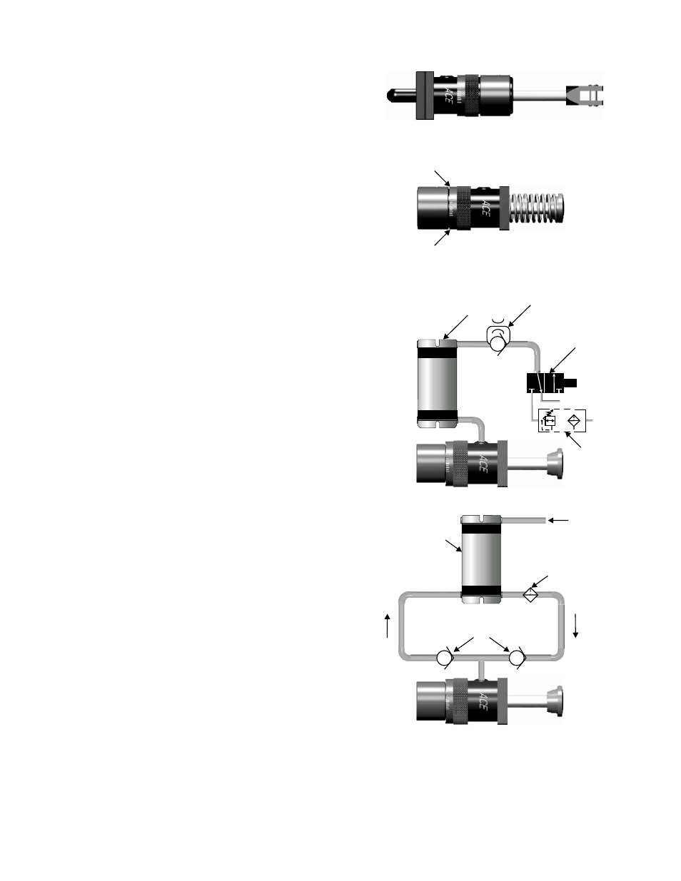
CLEVIS MOUNTING INSTALLATIION (Figure 4)
Fasten the rear clevis and the rod clevis to the mating
clevis members of the equipment. Make sure the shock
absorber is using the full stroke (less the last 3/32 inch
or 2.5 mm) and not being bottomed out. Be sure that the
equipment cannot pull the rod out any further than the
shock absorber stroke will allow.
ADJUSTMENT
Proper adjustment is important to the efficient operation
of the shock absorber. All units are pre-set at the factory.
Cycle the equipment to impact the shock absorber and
rotate the adjusting ring to achieve smooth deceleration.
Rotate towards zero to increase cushioning and away
from zero if the initial impact is too hard (Figure 5). If the
final setting approaches zero (less than 1), a larger shock
absorber should be considered. Tighten the adjusting ring
lock screw after achieving the final setting.
AIR EXHAUST CIRCUIT FOR MODEL AHS SHOCK
ABSORBERS
This type of installation (Figure 6) is necessary when it is
desired to have the rod remain in the shock absorber after
decelerating the load. Use special care to avoid overfilling
the air-oil tank. If not built in, a special ACE check valve
should be used to eliminate “misting” of oil out of the air-oil
tank.
RE-CIRCULATING COOLING CIRCUIT FOR MODELS
AHS & AHSS SHOCK ABSORBERS
This type of installation (Figure 7) may be required when
ambient temperatures and/or cycle rates cause the shock
0
absorber to head up beyond 200 F. Use high pressure
(1,000 psi) check valves with a low cracking pressure
(5 psi). If a filter is to be used in this circuit, a 30 to 40
micron filter element with a 5 psi by-pass is recommended.
Consult factory for assistance.
Figure 4
9
0
Less
Cushioning
More
Cushioning
Figure 5
Figure 6
Special ACE
Check Valve
Air-Oil Tank
3-Way Normally
Closed Valve
Exhaust
Supply
Sol
Filter/
Regulator
Figure 7
High Pressure Check Valve
Optional Filter
Air-Oil Tank
Air Supply