Figure 4...clevis mount, Lock nut (lock securely), Ace form16, ma, ml, mc magnum – ACE Controls ACE ML 64 Adjustable Series User Manual
Page 2
M
A
4
5
5
0
2
C
O
N
T
R
O
L
S
I
N
C
.
S
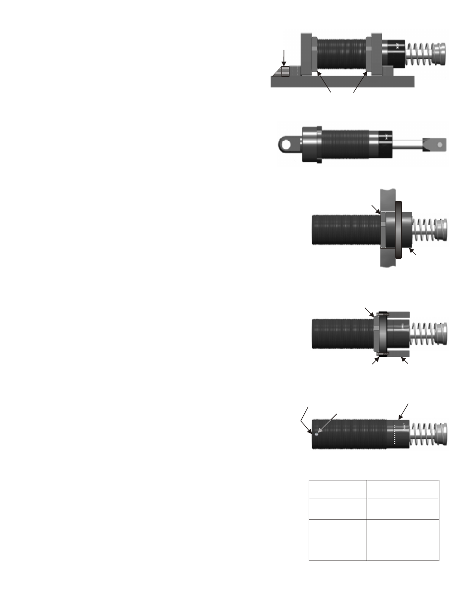
IDE-FOOT MOUNT INSTALLATION (Figure 3)
Thread lock nuts onto shock absorber. Thread shock
absorber into side-foot mounts. Install lock nuts securely.
Bolt side-foot mount assembly to the mounting structure.
Assure that the bolts are securely tightened. In order to
prevent movement of the side foot-mount assembly,
weld a key into position behind the rear foot bar.
CLEVIS MOUNT INSTALLATION (Figure 4)
Fas
ten the rear clevis and the rod clevis to the mating clevis
members of the equipment. Assure that the equipment cannot
pull the rod out any farther than the shock absorber stroke will
allow.
FLANGED STOP COLLAR INSTALLATION (Figure 5)
Thread shock absorber into flanged stop collar. Front edge
of flanged stop collar is opposite the internal threaded end of
flanged stop collar.
Front edge of integral shock absorber stop collar should be
directly aligned with front edge of flanged stop collar. Thread
lock nut onto shock absorber. Install lock nut securely against
rear surface of flanged stop collar. Bolt flanged stop collar to
mounting surface. Horizontal alignment of the bolts is preferred.
ADDING STOP BARS TO FRONT FLANGE MOUNT
APPLICATION (Figure 6)
Mount stop bars to flange. Thread shock absorber into flange.
Front edge of stop bars should be directly in line with front
edge of stop collar. Thread lock nut onto shock absorber.
Install lock nut securely against rear surface of flange. Refer to
the Torque Specifications chart, Figure 8.
ADJUSTMENT FOR MA, ML 33, 36, 45 AND 64 SERIES (Figure 7)
Proper adjustment is important to the efficient operation of the
ACE adjustable shock absorber. All units are preset at the factory
at 5.
After installation of the shock absorber, cycle the machine a
number of times. Turn the front stop collar or the rear adjuster
against the scale marked 0 to 9 until optimum deceleration is
achieved. (i.e. smooth deceleration throughout the stroke).
If hard impact is experienced at the start of the stroke, turn
the adjuster toward 9. If hard set-down is experienced at
the end of stroke, turn adjuster toward 0. If the final setting
is less than 2 or greater than 8, a different shock absorber
should be utilized.
Be sure to tighten the lock screw, (64 Series models only), on the
side of the shock absorber to secure the adjustment setting.
Torque the lock screw to 12 ft-lbs. (16 Nm). Failure to do this may
result in a shift in the adjustment setting during deceleration.
A 5/64 (2 mm) allen/hex bit wrench is required.
TORQUE SPECIFICATIONS CHART (Figure 8)
Refer to the Torque Specifications chart for the proper
torque when installing the shock absorber lock nut.
Model
MC, MA, ML
33, 36 Series
MC, MA, ML
45 Series
MC, MA, ML
64 Series
Torque/Lock Nut
54-59 ft-lbs
(74-81 Nm)
167-183 ft-lbs
(225-250 Nm)
560-610 ft-lbs
(755-830 Nm)
Figure 3..Side-Foot Mounting
Figure 5...Flanged Stop Collar
Figure 6...Stop Bars
M
A
4
5
5
0
-
2
C
O
N
T
R
O
L
S
I
N
C
.
M
A
4
5
5
0
-
2
C
O
N
T
R
O
L
S
I
N
C
.
Lock Nut
(Lock Securely)
Figure 7...Adjustment
Figure 8...Torque Specifications
M
A
4
5
5
0
-2
C
O
N
T
R
O
L
S
I
N
C
.
0
3
1
2
4
5
7
8
6
9
Adjuster
(Rear)
Tighten lock screw to
secure adjustment
(64 Series only)
Adjuster
(Front)
Stop Bar
Flange
M
A
4
5
5
0
2
C
O
N
T
R
O
L
S
I
N
C
.
Lock Nut
(Lock Securely)
Lock Nut
(Lock Securely)
Welded
Key
Flanged
Stop Collar
Figure 4...Clevis Mount
APPLYING APPROPRIATE TORQUE WITHOUT CALIBRATED TOOLING
The following procedure may be utilized if calibrated tooling is not available
to torque lock nut. Note: it is assumed that all necessary installation
instructions have been followed prior to this procedure.
1. After positioning the shock properly in relation to the accessory (i.e. flange,
collar, etc.) or mounting surface, with the proper adhesive (if applicable),
finger tighten the lock nut against the accessory or mounting surface until it
can no longer be turned.
2. Using appropriate equipment, tighten the lock nut until it rotates 1/8 to 1/4
of a full rotation (45 to 90 degrees) from the finger tight position. ACE has
determined that a lock nut secured in this manner meets the torque specifications
listed in the chart on the right.
Note: flanges, stop bars, flanged stop collars, side-foot mount and clevis mount assemblies are available from ACE Controls
directly or through distributors. See the ACE main catalog or visit the ACE web site for stocking distributors.
ACE Form16, MA, ML, MC Magnum