Automation Components ACI/TTU1000 User Manual
Page 8
2305 Pleasant View Rd. Middleton Industrial Park Middleton, WI 53562
PH: (608) 831-2585 FAX: (608) 831-7407
II-23
n
TROUBLESHOOTING
No reading
No power to board - check voltage at power terminal - should be between +8 and 35 VDC
Reading too low
RTD wires shorted - check with ohmmeter - should be close to either 100 or 1000 Ohms
Improper range of transmitter (too low) - check current - should be between 4 and 20mA
Reading too high
RTD opened - check with ohmmeter - should be close to either 100 or 1000 Ohms
Improper range of transmitter (too high) - check current - should be between 4 and 20mA
RF Interference
Input power must be clean. Use twisted wires or shielded cable. RF resistant power supply
Use a shielded cable to connect the sensor -- connect the shield to ground
Encase the board in a RF shielded enclosure
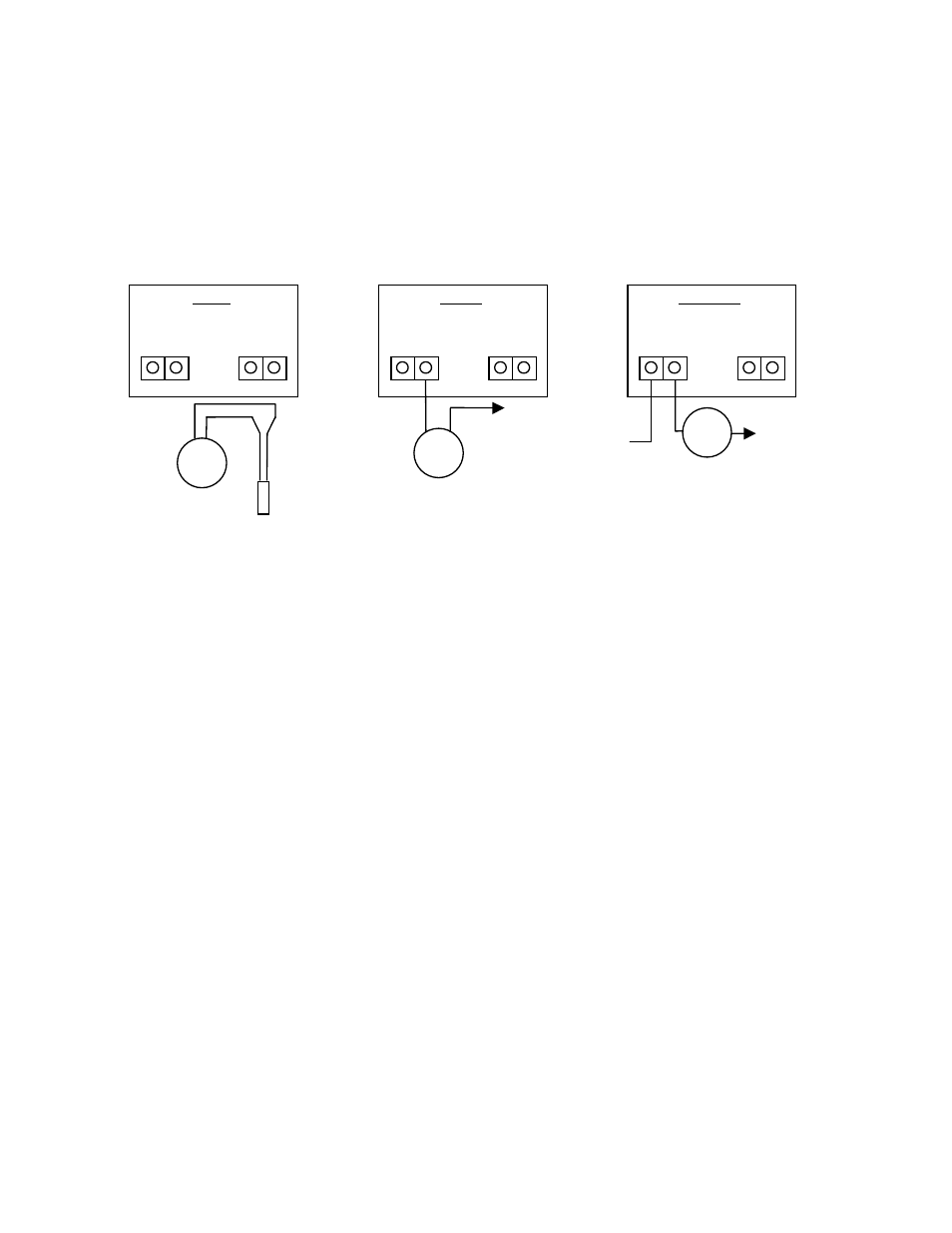
Ohm
Meter
OHMS
Disconnect RTD before
testing sensor resistance
VOLTS
Measure across the - of the
temp transmitter and common
Red
Lead
Black
Lead
Volt
Meter
Black
Lead
Red
Lead
+ -
+1 to 5 VDC / +2 to 10 VDC
Output
CURRENT
Disconnect (-) and place
meter in Series
~ 100 Ohm or
~ 1000 Ohm
Current
Meter
Power
Supply
To Controller
Input or Power
Supply Common
+4 to 20 mA
Output
Black
Lead
Red
Lead
RTD
Power Supply /
Controller Common