Duct mounting configuration, Figure # 9 – Automation Components ACI/TTU1000 User Manual
Page 5
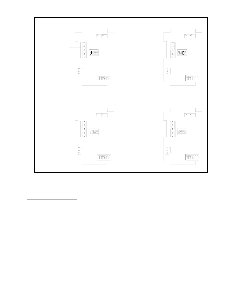
+15 to 36 VDC Input / 4 to 20mA Output
+15 to 36 VDC Input / 0 to 5 VDC Output
+24 VAC Input / 0 to 10 VDC Output
+24 VAC Input / 4 to 20mA Output
+15 to 36 VDC Supply Voltage
4 to 20mA Output
Supply Ground / Common
+24 VAC Supply Voltage
0 to 10 VDC Output
0 to 5 VDC Output
Supply Ground / Common
+15 to 36 VDC Supply Voltage
Figure # 9
SW3
ON
Green Wire
BLK Wire
Red Wire
J2
4
3
2
6
5
1
4
3
SW2
ON
2
1
Vout
GND
VDC
4-20
Zero Span
Green Wire
BLK Wire
Red Wire
+24 VAC Supply Voltage
4 to 20mA Output
4-20
VDC
Vout
GND
J2
Span
2
4
3
SW3
Zero
ON
1
6
5
4
SW2
ON
1
3
2
Green Wire
BLK Wire
Red Wire
4-20
VDC
Vout
GND
J2
Span
2
4
3
SW3
Zero
ON
1
6
5
4
SW2
ON
1
3
2
Green Wire
BLK Wire
Red Wire
4-20
VDC
Vout
GND
J2
Span
2
4
3
SW3
Zero
ON
1
6
5
4
SW2
ON
1
3
2
Supply Ground / Common
Temperature Sensor Connections (For RH/Temperature Sensor Combination Units only)
All of the connections to the temperature sensor connections should be made to the (2 or 3) 22 AWG 24” Flying Lead
wires using wire nuts or crimp style connectors. Please note that the wire colors will change depending on the type and
value of the sensing element used.
Duct Mounting Configuration:
The RH transmitter should be placed away from areas of excessive moisture, corrosive fumes, vibration, or extremely
high temperatures. All of the RH sensors have a +/- 3% interchangeability. It is recommended to do a single point
calibration for a much higher accuracy.
1. Drill a ¾” diameter hole in the duct where the sensor is to be mounted.
2. Now insert the stainless steel probe into the hole until the foam is in direct contact with the duct and attach
the RH transmitter by using the (2) #8 x ¾” self tapping TEK screws that are included with the installation
instruction.
3. Remove the cover and install your conduit connectors or watertight fittings. The outer ring should be used
when using a ½” NPT conduit fitting. Please note that the inner ring will knockout first and then the
outer ring should be tapped in (1) or (2) locations with a screwdriver before it can be peeled out. The
cover will be connected to the housing by the RH sensor leads. To remove the RH sensor leads from the
housing see Figure #8.
4. Next connect all of the wires to the corresponding terminal blocks and/or flying leads the wires to the
corresponding terminal blocks as shown in Figure #7 and Figure #9.
2305 Pleasant View Rd. Middleton Industrial Park Middleton, WI 53562
PH: (608) 831-2585 FAX (608) 831-7407
I0000145 Rev1.Doc