Automation Components ACI/RH TUCH LCD Room Unit User Manual
Automation Components Humidifiers
2305 Pleasant View Rd. ● Middleton Industrial Park ● Middleton, WI 53562
PHONE (608) 831-2585 ● FAX (608) 831-7407
I0000511 REV 1 11/13/2008
Page 1 of 3
Installation and Operation Instructions
ACI/RH TUCH LCD Room Unit
GENERAL INFORMATION
The ACI/RH TUCH LCD Room Unit is factory-
configured to support your specific requirements.
CAUTION
• CHECK THAT THE ACI/RH TUCH LCD ROOM
UNIT IS CORRECTLY CONFIGURED FOR THE
APPLICATION; CONTACT ACI IF YOU ARE
UNSURE.
• THE ACI/RH TUCH LCD ROOM UNIT IS A
PRECISION INSTRUMENT; PLEASE HANDLE
IT WITH CARE!
MOUNTING INSTRUCTIONS
Separate the cover from the base. Attach the base
directly to drywall, or to a standard 2” x 4” junction box
using the mounting hardware provided. Refer to the
wiring instructions to make the necessary connections.
After wiring, attach the cover to the base and turn the
(2) hex-screws at the bottom of the base until the cover
cannot be removed.
WARNING
• REMOVE POWER BEFORE WIRING! NEVER
CONNECT OR DISCONNECT WIRING WITH
POWER APPLIED. DO NOT ALLOW LIVE
WIRES TO TOUCH THE CIRCUIT BOARD!
CAUTION
• WIRING MUST COMPLY WITH APPLICABLE
LOCAL AND NATIONAL ELECTRICAL
REGULATIONS.
• DO NOT RUN THE ACI/RH TUCH LCD ROOM
UNIT WIRING IN ANY CONDUIT WITH
MAINS POWER SYSTEM WIRING.
• ACI RECOMMENDS USING A SEPARATE UL-
LISTED CLASS 2 TRANSFORMER WHEN
POWERING THE ACI/RH TUCH LCD ROOM
UNIT WITH 24VAC! FAILURE TO WIRE
DEVICES WITH THE CORRECT POLARITY
WHEN USING A SHARED TRANSFORMER
MAY RESULT IN DAMAGE TO ANY DEVICE
POWERED BY THE SHARED TRANSFORMER.
WIRING INSTRUCTIONS
The number of wires needed to connect the ACI/RH
TUCH LCD Room Unit to a controller depends on the
application. Most applications require three wires to
support the RH output, power, and ground (common).
All signals are common ground referenced. ACI
recommends 16-22 AWG twisted pair wires or
shielded cable for all sensor installations. Be sure to
connect the cable shield to the ground at the
controller ONLY.
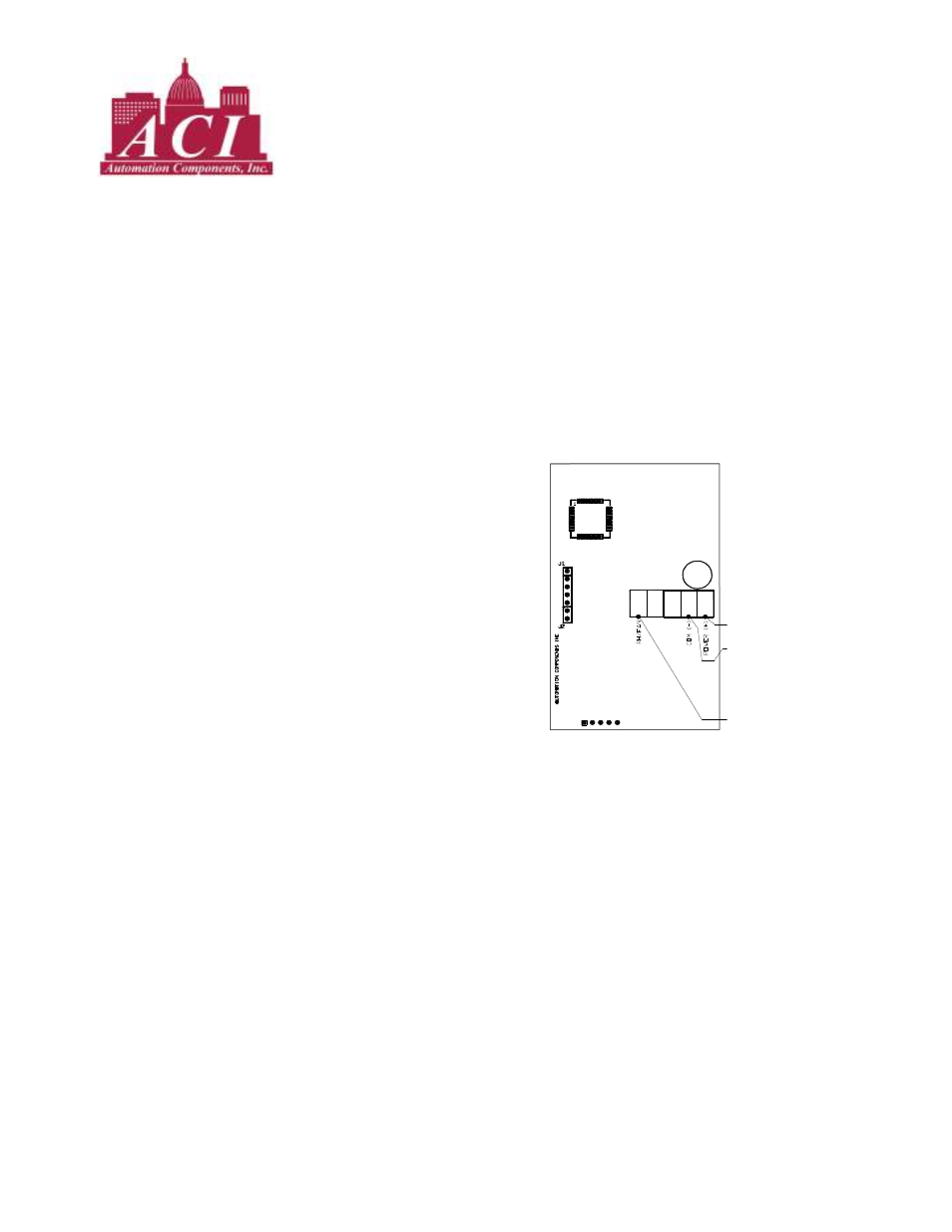
WIRING DIAGRAM
RH/FAN
RH signal to controller.
COM (-)
Ground or signal common, 20-28Vac (-).
POWER (+)
+15 to +30VDC, or 20-28Vac (+). See notes.
NOTES:
1. If the ACI/RH TUCH LCD Room Unit has any output configured as 0-10V
or 2-10V, the voltage at the POWER(+) terminal must be at least +18VDC.