Automation Components ACI/TTU1000 User Manual
Ac i, N = i ma 22
Installation and Operation Instructions
ACI/TT100, ACI/TT1000
ACI/TTM100, ACI/TTM1000
ACI/TTU100, ACI/TTU1000
2305 Pleasant View Rd. Middleton Industrial Park Middleton, WI 53562
PH: (608) 831-2585 FAX: (608) 831-7407
II-21
A
C
I
utomation
omponents
nc.
READ THESE INSTRUCTIONS BEFORE YOU BEGIN INSTALLATION
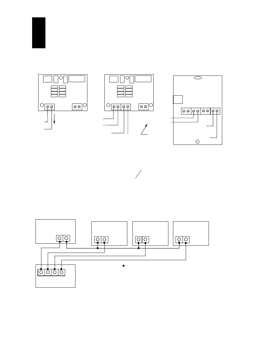
WIRING
Power
RTD
24VDC
OR
24 VAC*
1-5VDC
2-10VDC
Output
Power
RTD
4-20mA
Out
+24 VDC
4 to 20 mA Current Output
+
24VDC
-
Current
4-20mA
Voltage
1-5, 2-10VDC
Room Transmitter
with Setpoint and Override
Analog Input Common
For the 4-20 mA
Setpoint Only!
O/R
+
Set
-
-
T
+
4 to 20 mA Temperature
Output to Controller
+8 to 35 VDC
All ACI/TT and TTM temperature transmitters can be powered from either an unregulated or regulated +8 to 35VDC
power supply. Several transmitters may be powered from the same supply as shown below. Each transmitter could
draw 22mA. To determine the number of transmitters use the following formula:
N = I mA
22
where: N = number of transmitters
I = current available from power supply
22mA = maximum current draw of transmitter
e.g.,
If I = 1.5A then:
N = 1.5/22mA
N = 68
Therefore a 1.5A power supply will safely power up to 68 transmitters.
All ACI/TT, TTM, and ACI/TTU temperature transmitters are non-polarity sensitive. That means that either the
positive and negative outputs of the power supply can be connected to either side of the power terminal block. ACI
transmitters will also accept AC power only if specified when ordering. The output must be specified as a +1-5 or
+2-10 for this option when ordering the transmitters.
Power Supply
+ -
+ -
+ -
Temp.Transmitter #1
Temp.Transmitter #N
Temp.Transmitter #2
-
VDC
+
Controller
Gnd In1 In2 In3
= Connections
In1 = Controller Input #1
In2 = Controller Input #2
In3 = Controller Input #3
* Must be ordered as 24 VAC input
Document Outline
- RH_duct_inst.pdf
- The ACI/RH Duct and Outside series transmitters are a universal Relative Humidity transmitter that can be powered with either a +15 to 36 VDC or 24 VAC supply voltage. The ACI/RH uses a half-wave bridge rectifier to convert the AC power to a useable DC voltage. Caution: When using a 24 VAC transformer, ACI recommends that you use an isolated transformer. If sharing the transformer with your controller, valve, actuator, or any other device, be sure to connect all of the devices with the proper polarity, since most controllers are earth grounded. Failure to do so may result in damage to the ACI/RH, your controller, or any other devices that are attached due to a ground loop problem.
- The ACI/RH Duct and Outside transmitters are designed with a field selectable 4-20 mA, 0-5 VDC, or 0-10 VDC output signal that is equivalent to 0 to 100% RH. Unless specified upon ordering, all units are shipped from the factory to accept DC power with a 2-wire, 4-20 mA loop-powered output. Caution: When changing the Output Selection Switch (SW3) make sure that the power supply is turned off before making any changes. Failure to do this may cause damage to the unit.