Assembly instructions, Step 1] assembling a-base(s), Step 2] attaching a-base supports – Martin Universal Design U-7200C Royal Elm Designer Table User Manual
Page 2: Step 3] attaching channelled side, Step 4] adding lower support & rod
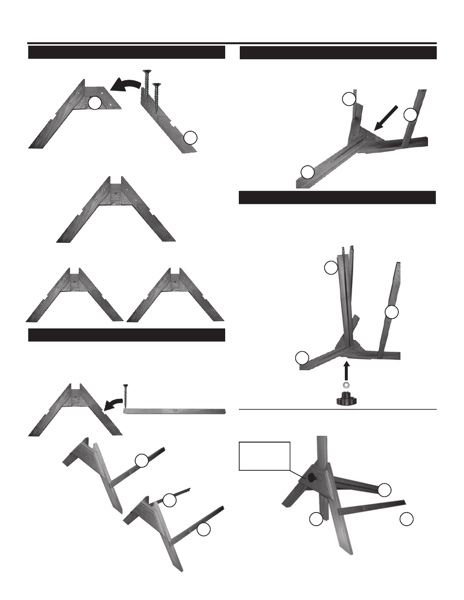
STEP 1] Assembling A-Base(s)
Assembly Instructions:
A-Base end [A]
Left Leg [B]
Position the Left Leg [B] onto the A-Base, lining up holes.
Secure with [2] Long Wood Screws. Tighten. See below for
proper assembly.
Long Wood
Screws [GG]
Repeat with other side.
Now, you should have [2] complete A-Base Assemblies.
STEP 2] Attaching A-Base Supports
Proper assembly of
A-Base & support.
STEP 3] Attaching Channelled Side
Repeat with other support.
Attach as shown to right.
B
A
D
C
C
C
C
C
STEP 4] Adding Lower Support & Rod
A-Base Cross Supports [C]
A-Base Assembly
After securing with washer [EE] and Female Knob [CC],
turn assembly up onto base as shown below.
C
F
F
C
D
D
Washer [EE]
and Female
Knob [CC]
Created July 06 - RPI
Take one assembled A-Base end and attach [1] support
bar (with Logo reading up in correct position) and place into
notch and secure with [1] long wood screw [GG]. See below
for proper assembly.
With above assembly still laying flat on surface, insert one
end of Channeled Cross Member with Threaded Rod [F]
into Channelled Side Support [D] making sure rod end goes
through other end of A-base assembly. Secure with Washer
[EE] and Female Knob [CC]
Take A-Base end that has the two supports attached and
place on flat surface. Position Channelled Side Support [D]
into middle section of A-Base. Making sure channel is on
bottom end. As shown below.
Take the A-Base end [A] as shown below and the Left Leg
[B] for the A-Base.
Pg. 2