Berkeley u-ds1400c top assembly instruction, Instructions for 36” x 48” p top, This is the top included in the u-ds1400c package – Martin Universal Design U-DS14 BERKELEY TABLE User Manual
Page 2
Step 1. Place top onto carpeted floor. Laying best surface face down.
Step 2. Attach Left and Right Metal Guides [B] by: Measuring 9” in
from left edge and mark with pencil, repeat with right side.
See above illustration. Measure 2.75” from front edge and
make pencil mark. Repeat with other side for Metal Guides.
Mark holes and then break surface with nail or awl. Secure
with [3] Phillip screws [E] per metal guide [B].
Step 3. Attaching Left and Right Brackets (already attached to base)
by: Measuring 9” in from left edge and mark with pencil,
repeat with right side. See above illustration. Measure 3.75”
from rear edge and make pencil mark. Repeat with other side
for Brackets. Break surface with nail or awl. Repeat with right
side. Secure with [4] Phillip Screws.
Please Note:
Reason for breaking top surface by tapping a nail or awl in screw
holes, is to make starting hole in surface to allow for easier attach-
ment of screws.
Instructions for 24” x 36” B Top
Instructions for 30” x 42” C Top
Bracket
Bracket
Step 1. Place top onto carpeted floor. Laying best surface face down.
Step 2. Attach Left and Right Metal Guides [B] by: Measuring 6” in
from left edge and mark with pencil, repeat with right side.
See above illustration. Measure 2” from front edge and make
pencil mark. Repeat with other side for Metal Guides. Mark
holes and then break surface with nail or awl. Secure with [3]
Phillip screws [E] per metal guide [B].
Step 3. Attaching Left and Right Brackets (already attached to base)
by: Measuring 5-5/8” in from left edge and mark with pencil,
repeat with right side. See above illustration. Measure 3” from
rear edge and make pencil mark. Repeat with other side for
Brackets. Break surface with nail or awl. Repeat with right side.
Secure with [4] Phillip Screws.
Please Note:
Reason for breaking top surface by tapping a nail or awl in screw
holes, is to make starting hole in surface to allow for easier attach-
ment of screws.
Metal
Guide
Metal
Guide
Instructions for 31.5” x 48” D Top
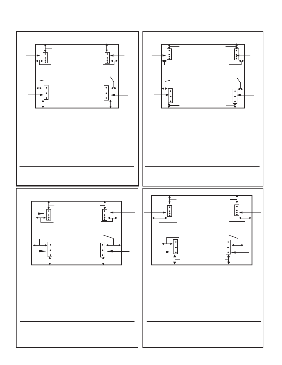
Step [2] 9” from left side to
left edge of
Metal Guide
Step [2] 9” from right side to
right edge of Metal Guide
Step [2] 2.75” from front edge
Step [3]
8-5/8” from left
edge
Step [3]
8-5/8” from
right edge
Step [3] 3.75” from back edge
Bracket
Bracket
Metal
Guide
Metal
Guide
Instructions for 36” x 48” P Top
Step [4] 5.5” from front edge
Step [3]
8-5/8” from
left edge
Step [3]
8-5/8” from
right edge
Step [5] 5.5” from back edge
Bracket
Bracket
Step [2] 9” from left side to
left edge of
Metal Guide
Step [2] 9” from right side to
right edge of Metal Guide
Step 1. Place top onto carpeted floor. Laying best surface face down.
Step 2. Attach Left and Right Metal Guides [B] by: Measuring 9” in
from left edge and mark with pencil, repeat with right side.
See above illustration. Measure 5.5” from front edge and
make pencil mark. Repeat with other side for Metal Guides.
Mark holes and then break surface with nail or awl. Secure
with [3] Phillip screws [E] per metal guide [B].
Step 3. Attaching Left and Right Brackets (already attached to base)
by: Measuring 9” in from left edge and mark with pencil,
repeat with right side. See above illustration. Measure 5.5”
from rear edge and make pencil mark. Repeat with other side
for Brackets. Break surface with nail or awl. Repeat with right
side. Secure with [4] Phillip Screws.
Please Note:
Reason for breaking top surface by tapping a nail or awl in screw
holes, is to make starting hole in surface to allow for easier attach-
ment of screws.
BERKELEY U-DS1400C TOP ASSEMBLY INSTRUCTION
Created 06/06 RPI
If you purchase optional Tops B, D or P use the appropriate instruction for the top assembly.
Step 1. Place top onto carpeted floor. Laying best surface face down.
Step 2. Attach Left and Right Metal Guides [B] by: Measuring 3” in
from left edge and mark with pencil, repeat with right side.
See above illustration. Measure 1.25” from front edge and
make pencil mark. Repeat with other side for Metal Guides.
Mark holes and then break surface with nail or awl. Secure
with [3] Phillip screws [E] per metal guide [B].
Step 3. Attaching Left and Right Brackets (already attached to base)
by: Measuring 2-5/8” in from left edge and mark with pencil,
repeat with right side. See above illustration. Measure 1.25”
from rear edge and make pencil mark. Repeat with other side
for Brackets. Break surface with nail or awl. Repeat with right
side. Secure with [4] Phillip Screws.
Please Note:
Reason for breaking top surface by tapping a nail or awl in screw
holes, is to make starting hole in surface to allow for easier attach-
ment of screws.
Step [3] 1.25” from back edge
Bracket
Bracket
Step [3]
2-5/8” from left
edge
Step [3]
2-5/8” from
right edge
Step [2] 3” from left side to
left edge of Metal Guide
Step [2] 3” from right side to
right edge of Metal Guide
Metal
Guide
Metal
Guide
Step [2] 1.25” from front edge
Step [2] 2” from front edge
Metal
Guide
Metal
Guide
Step [2] 6” from left side to
left edge of Metal Guide
Step [2] 6” from right side to
right edge of Metal Guide
Step [3] 3” from back edge
Step [3]
5-5/8” from
left edge
Step [3]
5-5/8” from
right edge
This is the top included in the U-DS1400C Package