Ridgeline_assem(steps_2), Ridgeline, Assembly – Martin Universal Design U-DS6000P Ridgeline Table User Manual
Page 4
Assembly
Since 1853
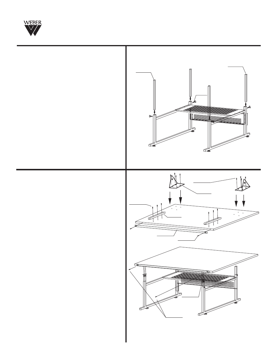
STEP 4
Attaching Height Adjustment Tubes.
To attach the height adjustment tubes
(part D + part F), use 4 each (part I) knob.
Leave a 12” gap from the top of the
side supports, and secure the tubes in place
by tightening the tubes with the knobs.
See Fig 4
FIG 4
Dx2
Ix4
Fx2
Ridgeline
E
Hx8
E
O
PX2
QX2
STEP 5A
Attach (part Q), metal guide, by using 6 each
4x14mm screws (part H).
See Fig 5
FIG 5
STEP 5B
See Fig 5
Attach (part O) pencil edge to your desired
position using 2 each 4x12mm screws (part P).
There are no pre-drilled holes for pencil edge.
Attach (part G), tilt mechanism, by using
8 each 4x14mm screws (part H).
See Fig 5
STEP 5C
GX2
HX8
PX2
HX6