Quick Cable 800 Amp Booster Clamps Cable Assembly and Safety User Manual
Page 2
6. Heavy Wall Copper Lugs. Based on cable selected, use the appropriate heavy wall copper lugs below One lug is
required for one booster clamp. Four lugs are required for the typical set of booster cables. (The part numbers below
are for a box with five lugs.)
5. Guideline for Cable Gauge. For the proper gauge booster cable for your vehicle, please check your owner’s manual.
If this information is not available, use the following as a guideline. Important: the gauge size of your booster cables
should be larger than the largest and longest cable in your vehicle.
Cable Carrying Capacities
25’ (7.6M) Booster Cables
For Intermittent Duty Only (Not Continuous Duty)
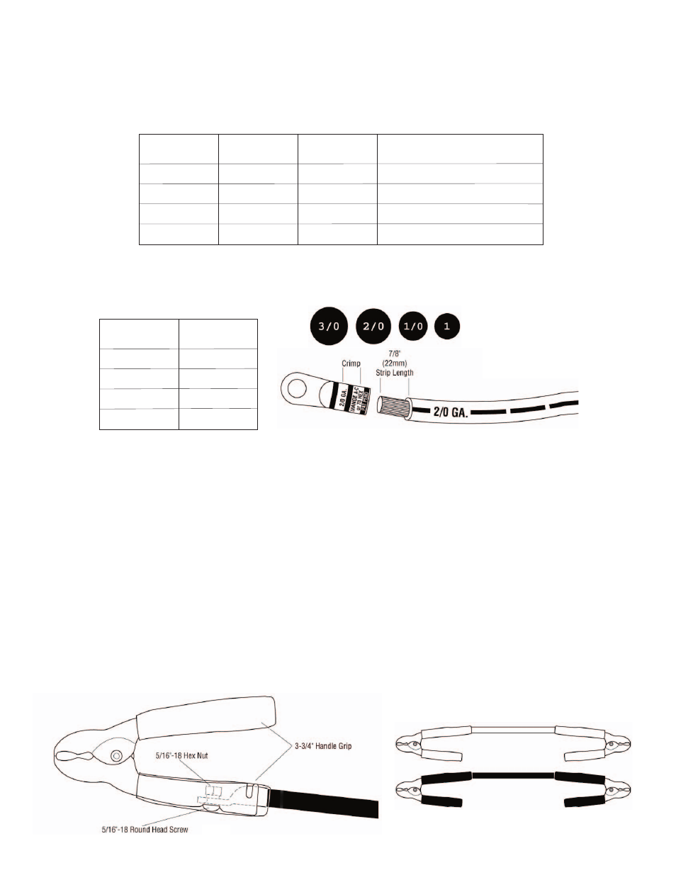
The size bullets (left) will help
you determine the gauge (size)
of an unmarked cable.
Measure the bare conductor
only, not the insulation. Actual
diameters vary depending on the
specific stranding of the wire.
Fig. 1
Copper Cable
Gauge
1/0 Gauge
Up to 400 Amps
500 Amps
600 Amps
700 Amps
300 Amps
325 Amps
375 Amps
425 Amps
Full-size Car or Van
Light Truck, Light Construction, Small Tractor
Tractor, Truck, Bus, Construction
HD Tractor, Off Highway
2/0 Gauge
3/0 Gauge
Made of
Battery Cable
Typical Vehicle
1 Gauge
Made of
Welding Cable
Part Number
4810-005F
1 Gauge
1/0 Gauge
2/0 Gauge
3/0 Gauge
4820-005F
4830-005F
4801-005F
Fits Cable Gauge
Fig. 2
7. Slide the handle grip onto and away from the end. Strip 7/8” to 1” (22 - 25 mm) of insulation from end of cable.
Insert bared wires into barrel of lug. Crimp lug on to cable. Use two crimps on barrel for best connection. See
Figure 1.
8. One handle of the booster clamp is formed so that the heavy wall lugs will nest inside. Bolt the lug into place
according to Figure 2.
9. Slide the 3-3/4" (95mm) handle grip down over the handle and lug, according to Figure 2.
The handle grip tube will seal the cable, reducing corrosion, and it will also act as a strain relief for the cable, extend-
ing the life of your booster cable.
10. Push the other handle grip onto the other handle. Make certain the grips are the same color on both handles. See
Figure 2.
11. For a typical set of booster cables, install a second clamp on the other end of the cable. Make certain the same color
handle grip is used for both clamps on the same length of cable. Use black grips for the negative booster cable. Use
red grips for the positive cable. See Figure 3.
Note: For longer booster cables, increase the gauge of the cable.
Fig. 3