Vaddio Recessed Ceiling Conversion User Manual
Page 3
CeilingVIEW Recessed Ceiling Installation Kit 341-264 Rev. B
Page 3 of 6
INSTALLATION
The CeilingVIEW products are integrated document/object cameras specifically designed for installation
above a conference table, lectern or work surface. Recommended ceiling height range is between 8’ and 12’
(2.44m to 3.66m). Make sure the measurements used for rough-openings, image orientation and location
are 100% accurate prior to attempting installation (measure twice, cut once).
Before Installing
• Check above the ceiling tile or drywall where you plan to install the camera to make sure the area is
clear and that there is adequate room for the CeilingVIEW Module and all of its components.
• Pre-wire all cabling as required.
• Please check the individual Vaddio CeilingVIEW Installation and User Guide manuals for special
considerations pertaining to operability specific to the models used (i.e. the CeilingVIEW Document
Cameras, used as part of a multi camera system, are required to be the last camera in the control chain
to support the VISCA daisy chain control standard).
Camera Module Cut-outs
The following table contains the cutout dimensions for the recessed CeilingVIEW back box enclosures.
TABLE 1:
Vaddio Camera & Part Number
Rough-opening
Square Dimension
Recessed
Installation Kit
CeilingVIEW 70 PTZ
9-1/4” (23.495cm)
535-2000-210
CeilingVIEW 70 PTZ HideAway
9-1/4” (23.495cm)
535-2000-210
CeilingVIEW SD & CCU
6” (15.24cm)
535-2000-226
CeilingVIEW HD & CCU
6” (15.24cm)
535-2000-226
MOUNTING INSTRUCTIONS
The Recessed Ceiling Installation Kits can be installed in finished ceilings, as long as there are no
obstructions above the drywall, or in new ceilings as long as the camera position, orientation and location
over work surfaces is determined prior to installation.
PRE-INSTALLATION INSTRUCTIONS
Pre-wire all cable as required. Cabling after the ceiling is closed up can be challenging and time consuming.
Step 1:
Attach a string or plumb bob to the ceiling where the camera is to be located. Position the string directly over
ample table space or work surface to allow easy document access and object positioning.
Step 2:
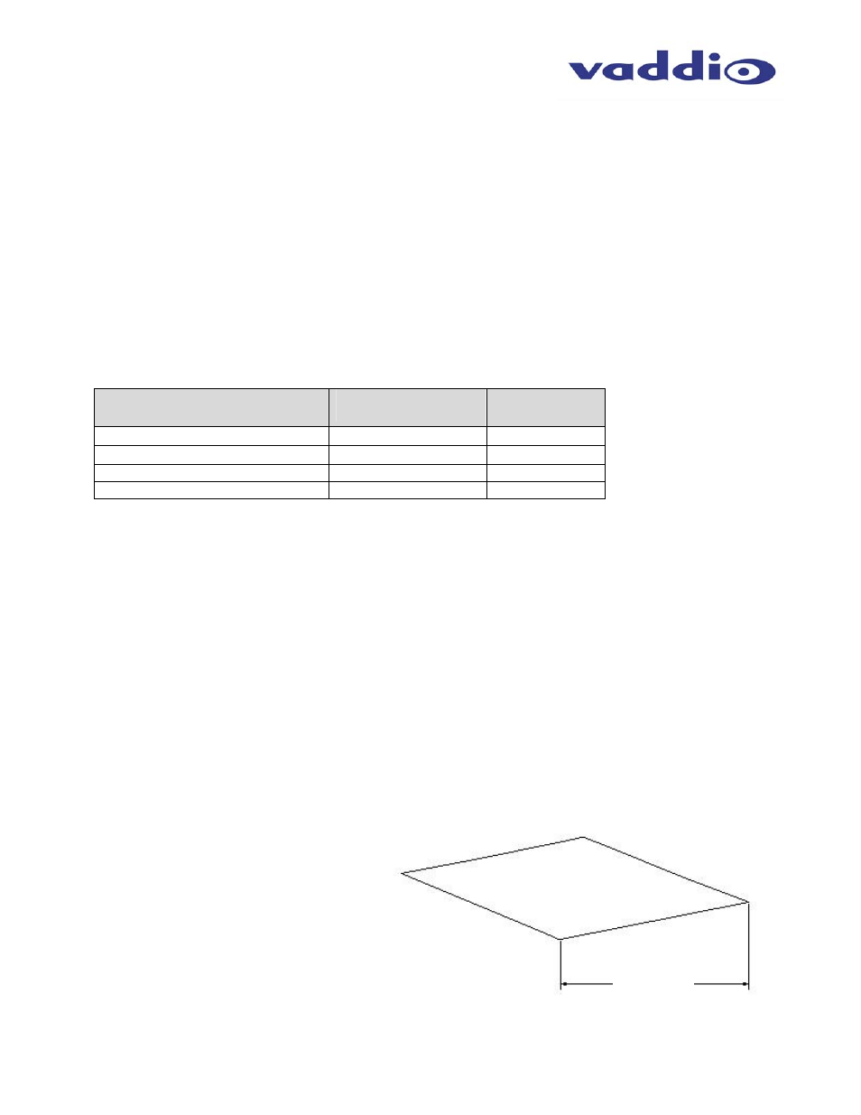
Draw the appropriate sized square (from Table 1) onto the drywall centered on the string. Cut out the
marked square or in the case of a new construction have the drywall contractor cut the drywall to the proper
dimension.
See Table 1
Figure 4:
Mark and cut the square in the
drywall for the appropriate camera