System layout and components – Pulsafeeder Polymer Makedown Systems EN User Manual
Page 6
Manual Polymer Makedown Systems
Installation, Operation and Maintenance Manual
72-910-MPMDS-E Rev A
Skid Layout and Components
Page 6
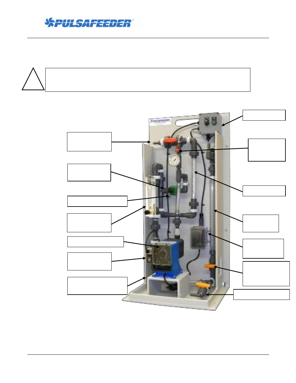
System Layout and Components
Figure 1, below, illustrates a static mixer polymer makedown system with integrated control. Note the
various components and their descriptions as they apply to your system.
Control Panel
Calibration
Column
Flow Indicator,
Water
Static Mixer
Back Pressure Valve
Water Inlet, Left Side,
Back or Front
Made-down
Polymer Outlet
!
CAUTION
Never remove the Tank Cover without removing power to the Polymer
Makedown System first. The tank mixer blades (inside the tank) can cause serious
harm or even death if allowed to come in contact with a person during operation.
Neat Polymer
Injection Quill
Neat Polymer Inlet
Neat Polymer Pump
Pump Power
Supply
Calibration
Column Fill
Valve
Figure 1
Water Inlet
Solenoid Valve
Calibration
Column Supply
Valve