Wiring diagram, Caution, Fig.3-2 fig.4 – Panasonic FV-05VFL2 User Manual
Page 7: Fig.3-1, Fig. 5
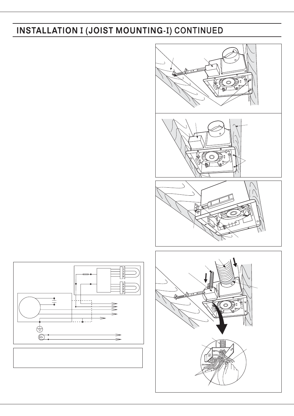
Fig.3-2
Fig.4
4. Install the suspension bracket to joists by using long
screws (M4X30) and secure it to the fan body by
using screw
(M4X12) (Fig.4)
II
Fan body
Joist
4-Long screws(M4X30)
Joist
Fan body
2-Long screws
(M4X30)
2-Long screws
(M4X30)
screw
(M4X12)
II
7
5. Remove junction box cover and secure conduit or
stress relief to junction box knock-out hole. (Fig.5)
6. Refer to wiring diagram below.
Using wire nuts, connect house power wires to
ventilating fan wires:
black to black; white to white; green to green;
Replace the junction box cover.
CAUTION:
Mount junction box cover carefully so that lead
wires are not pinched.
7. Install a circular duct (using 4 inches duct or 3 inches
duct) and secure it with duct tape or clamps.
Fig.3-1
3. Install the suspension bracket and the flange of fan body
to joists by using long screws (M4X30) ( If spacing A
between joists is 10 1/4~12 inches, install the flange of
fan body according to Fig.3-2, others according to
Fig.3-1 install the product)
Wiring diagram
Motor
Moteur
Fan unit
Red
Black
W ite
h
Green
Capacitor
Junction box
Green
Black
w ite
h
Lamp
Light unit
Power Supply
AC120V 60Hz
Earth ground
Earth ground
Black
White
Night Lamp
Power Supply
AC120V 60Hz
Current Fuse
Electronic
Ballast
W ite
h
Junction box cover
Fig. 5
Conduit
Circular duct
Wire nut
Conduit
Junction box
Green wires
Lead wires
Duct tape
or clamps